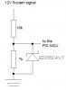
Can you bring 12V signal directly to the MCU port? If I am not mistaken MCUs have its internal resistance, and we musn't overide maximum current through MCU's. So can we bring 12V directly to MCU, maybe adding simple resistor or do we need optocoupler in case when signals are higher than MCU operating voltage (5V).
Continue to Site