Continue to Site

Welcome to our site!

Electro Tech is an online community (with over 170,000 members) who enjoy talking about and building electronic circuits, projects and gadgets. To participate you need to register. Registration is free. Click here to register now.

  • Welcome to our site! Electro Tech is an online community (with over 170,000 members) who enjoy talking about and building electronic circuits, projects and gadgets. To participate you need to register. Registration is free. Click here to register now.

Magnetic Field extending range

Status
Not open for further replies.

ProFPGA

Banned
Hi All ,

I need professional advice on a problem I am trying to solve . I am trying to sense electromagnetic field created by an iron-core coil from a distance of 12-feet. The Transmitter coil is 6-inches in length , #30 AWG wire is winded on it up the thickness of about 0.5 inches ( I don’t remember the number of turns ), its total impedance is 240ohms. See pic attached . I have a derive circuit in which a 555 is generating 25Hz of square wave its output is amplified by a LM1875 which is supplied +/- 25V to output amplified signal . The signal is fed into the winding and the other end is just grounded .

My Receive coil is a small with total impedance of 2.4Kohm because #44 AWG wire in winded on it , this coil is air core .

When I do testing I just connect both ends of Rx coil to the scope , I get very strong signals when Rx coil is line with either end of Tx coil because iron core amplifies the Magnetic field on both ends of Tx coil . I did some FEMM simulation and it shows that magnetic field should extend outwards beyond 14-feet . But I don’t see any signal or the FFT function of the scope doesn’t show any spike at 25Hz beyond 1-feet , although when Rx coil is inline with the end of TX coil I do see signal embedded in the noise . But my requirement is that Rx coil should detect 25Hz when place 12-feet away in length-wise parallel to the Tx coil .


I thank all in advance
 

Attachments

  • TXcoil_5x3inches_extended_range1.jpg
    TXcoil_5x3inches_extended_range1.jpg
    162.4 KB · Views: 190
By theory the waves go out forever. They will be too small for you to see them.
A iron core on the receiving end will make a 'directional antenna'.
You probably need more gain on the receiving end.
I think you are picking up 50 or 60hz from the power line. I think you need a 25hz band pass filter. or a low pass filter that passes 25 but rejects 50hz.
 
Can you use a Tx frequency which is not a multiple or sub-multiple of the mains frequency? Might make mains-frequency rejection in the Rx signal easier.
 
What are you trying to accomplish?

First off, a square wave is extremely harmonics rich: any attempt to achieve resonance (a vital component of EMF transmission), is a waste of time as a result. This is why EMF "carrier" transmission signals are (generally) sine waves (a pure, single frequency). You are, in essence, sending pulsed (the square wave) electronic NOISE from and to grossly mismatched antennae.

Secondly, without both your Tx and Rx inductors being (at the least roughly) equivalent in value, resonance will also be more difficult to achieve.

And with a wavelength of 12,000 meters, resonance is going to be awkward to get.
 
Last edited:
Hi ALL, i am not trying to light a bulb or charge something 8 feet away ,i just need to sense 25Hz from a distance of 8 to 12 feet away , i dont care even if its modulated RF i.e pulses of 25Hz but during 40ms of high its 4 or 5 Mhz pulses and when its low for another 40ms its silent .

How do i do that , any leads ???
 
Having spend a large number of years in digital domain i am very rusty in analogue electronics , so please dont mind my lack of knowledge
 
Hello,

First, magnetic fields are directional, so you may get a stronger signal with the coils oriented one way than another way. That's just the way magnetic fields are.

Second, 25Hz may be too low for the coils. If one of them saturates, the field decreases.

Third, to get a stronger signal going out, increase current. The signal strength is proportional to current, so if you double the current you double the signal. That's of course if your coil can take the current. If it cant, then you have to cut back on the duty cycle, and that means a faster pulse, and that means that you may need a higher voltage to drive the coil to that current level fast enough to actually get the peak current to happen.

On the receiving end, as others have said, a magnetically active core in the other coil should help too, and also the strength of the signal will increase with the number of turns.

The way to find out what you really need is to experiment. Holding the receive coil at a distance an measuring the signal, then changing something, then measuring again, then comparing measurements, will tell you if the change made things better or worse. If better, then you can move the coil out farther and try another change. Working like this you may be able to accomplish your goal of whatever distance you need.
 
Thanks a lot MrAI , your comments very insightful and really summed up my problem , i will work on these lines and get the max range , first i have to build a good 8-order Active filter with a gain of 6 on the receive side that will work on +/-5.0V and i will test it and see i have good results . To make things even harder the Tx coil circuit will be running off 03 D-cells i.e 6.0V , so my concentration would be make receive side circuit filter and pick faintest 25Hz , figers crossed
 
Hi ALL, i am not trying to light a bulb or charge something 8 feet away ,i just need to sense 25Hz from a distance of 8 to 12 feet away , i dont care even if its modulated RF i.e pulses of 25Hz but during 40ms of high its 4 or 5 Mhz pulses and when its low for another 40ms its silent .

How do i do that , any leads ???
OK.

This should explain why your current concept won't work for your desired range: **broken link removed**.

How about something like this: http://electronics-diy.com/am-radio-transmitter-using-555-chip.php

You would feed your 555 25kHz signal into the "Audio +" and Gnd.

For a Receiver (at its most basic):
upload_2015-4-1_9-15-57.png
**broken link removed**
Crystal sets take a bit of tuning, but this would work for your purposes, such as I understand them. You can buy them online for practically nothing.

Keep in mind that your are flirting with RF here, which generally requires some manner of an FCC license. But, at the signal strength you're likely to produce, it should not be a problem.

You would, in your case, eliminate the earphones and attach your scope probe (or whatever) directly to the Detector output.

<EDIT> If you were to use a simple "Ferrite Coil" type AM radio antenna, for both your rx and tx circuits, I think it'd work quite well.
 
Last edited:
Thanks a lot MrAI , your comments very insightful and really summed up my problem , i will work on these lines and get the max range , first i have to build a good 8-order Active filter with a gain of 6 on the receive side that will work on +/-5.0V and i will test it and see i have good results . To make things even harder the Tx coil circuit will be running off 03 D-cells i.e 6.0V , so my concentration would be make receive side circuit filter and pick faintest 25Hz , figers crossed

Hi again,

The current through the coil driven by a voltage source will follow this form:
I(t)=(1/R)*E*(1-e^(-(t*R)/L))

where E is the voltage, R is the resistance of the coil, L is the inductance of the coil, and t is time, and from this we see that the peak current is:
Ipk=E/R

So with 240 ohms for R and 6v for E we get only 25ma, which isnt much.

If we assume we are using a higher voltage and simplify we get this:
di/dt=E/L

which means the change in the current is equal to E/L, and that means the higher E is the faster the current will shoot up with a given fixed value for L (which your coil has).

So you see either way E affects the peak current quite a bit. Resistance also plays a big role when the voltage is low, but to get less resistance you need thicker wire.

An idea to get higher voltage from the batteries is to use a boost circuit. Boosting the voltage two times gives you twice the current.

What else we dont know though is the inductance of the coil. It's got a magnetically active core, and without knowing more details we cant calculate the inductance. This inductance will affect the design a lot if it is high because the higher the inductance the slower the change in current is that can occur. A couple tests would tell us what the inductance is if you have a scope handy.

As a rough guide, the higher the voltage is the more the voltage source starts to look like a current source and that means it pumps current faster into the coil. Of course the current peak and time duration has to be limited in this case, so it would be very similar to driving a stepper motor coil.

Just for reference, the true change in current with time is:
di/dt=(E/L)*e^(-(t*R)/L)

so it also does depend on R when the voltage is relatively low.

The difference between using a resonant circuit and a boost circuit to raise the voltage is the boost circuit would provide better control over the current though the coil.
 
Last edited:
Here are the results of testing Rx coil with a 8-order Sallen-key active filter , on the last stage of the circuit i ran out of accurate values of the capacitors or the sales guy from where i bought it didnt had 5% capacitor for those values , bottom line is it did cleaned the signal , but time domain trace dosent show anything except for over-riding noise, only when i plot FFT i see a nice spike at 25Hz at a distance of 6ft . see pics attached
 

Attachments

  • FilterCKT_Board1.jpg
    FilterCKT_Board1.jpg
    411.4 KB · Views: 169
  • FFT_25Hz1_edited.jpg
    FFT_25Hz1_edited.jpg
    45.2 KB · Views: 155
Actually my approach to extend the range of sensing is wrong to detect magnetic field at a distance of 12ft or more a Hall-effect sensor is used and to channel field into sensor metal strips are used to direct field into its sense axis , they work at low voltage and also Tx coil doesn't have to running on very high voltage and current , see pics attached
 

Attachments

  • DSC00026.JPG
    DSC00026.JPG
    86 KB · Views: 161
Hi,

Looks interesting. When i was experimenting with the linear hall effect devices several years ago, i found that any metal at all was better than no metal. Even one of those steel binder clips would help increase the sensitivity, but i also found that if you clamp one onto the hall effect device it breaks the plastic package as the plastic package can only take so much pressure before it cracks.

Do you have to use 25 Hz or can you go higher? When i did an IR remote control back in the 1990's i used something like 20kHz, and the 6th order filter was all passive, yet it still worked pretty well.
 
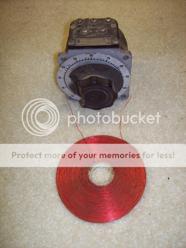
Try a different shape coil like this pancake, 1/4" thick, 6" diameter. I wound it with #24 wire, I have no clue how many turns it is, probably about 1000. This coil is directional like an antenna. If I connect it to a micro amp meter I can pick up very small magnetic fields around the house. I built 2 coils 1 to transmit and 1 to receive. One coil will send a signal to the other coil 25 ft away. It makes a good metal detector coil too. If i charge up a small capacitor about 1000uf 50vdc and discharge it into 1 coil the other coil picks up the signal from 25 feet.

100_1241_zps9mkq73gw.jpg
 
Last edited:
Status
Not open for further replies.

Latest threads

New Articles From Microcontroller Tips

Back
Top