Continue to Site

Welcome to our site!

Electro Tech is an online community (with over 170,000 members) who enjoy talking about and building electronic circuits, projects and gadgets. To participate you need to register. Registration is free. Click here to register now.

  • Welcome to our site! Electro Tech is an online community (with over 170,000 members) who enjoy talking about and building electronic circuits, projects and gadgets. To participate you need to register. Registration is free. Click here to register now.

Luminous response for a determined frequency

Status
Not open for further replies.
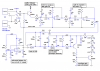
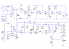
OK, here's the schematic. It has been simulated, but not built and tested. The gain range is huge. Let me know if the range needs to be reduced, or if the gain is too low (which I doubt). I drew options for a 2-wire or 3-wire electret mic. Radio Shack has both types on their web site, with little information on how to use them, and I have little experience with them. If anyone sees a problem, pipe up!
I put a little flat spot on the top of the bandpass filter (BPF) response to accommodate component tolerances and frequency drift from the nominally 2kHz source. This is the reason the twp BPF sections have different capacitor values. If I were building this, I would not relax the component tolerances, because it might mistune the BPF to the point where the sensitivity is impaired.
If you want to use something besides LEDs as your indicator, or you need more of them, or more current through them, etc., post your wishes.
Please let us know how this works if you build it.

Ron
 

Attachments

  • ice cream truck detector sch.PNG
    ice cream truck detector sch.PNG
    35.9 KB · Views: 163
Wow!

Thanks again Ron, as i said, i'm a old school in electronics and i barely remember... but i can see a very detailed and hard work in the picture.

I'm sure it will work, so hands on...

Now i will study the diagram and try to comprehend how it's work, then i will make the list of components to buy and prepare to build.

If it's no diference with the mics, i will use the two wired one... it's cheaper

Just a question: How can i calculate the frequency in the band pass filters?

Luix
____________________
Maybe I'm Undecided... Maybe not
 
It is a very nice circuit to detect the whistle used by Brit cops when they chase a bad guy.
I wonder how far beneath the street the ice cream guy drives his submarine?
 
audioguru said:
It is a very nice circuit to detect the whistle used by Brit cops when they chase a bad guy.
I wonder how far beneath the street the ice cream guy drives his submarine?
Could there be a market there, for deaf bad guys who want to know when the cops are chasing them? :D
 
Here's the frequency response.
 

Attachments

  • ice cream truck filter Bode.PNG
    ice cream truck filter Bode.PNG
    17.6 KB · Views: 158
Cats, squeaking brakes, and jet airplanes detector.
It will also detect the crying by the kid who dropped his ice cream cone.
 
audioguru said:
Cats, squeaking brakes, and jet airplanes detector.
It will also detect the crying by the kid who dropped his ice cream cone.
Hey, don't shoot the messenger!
I briefly thought about correlating the incoming signal with the WAV file - VERY briefly. :)
I'll bet, though, that the repetitive tone bursts are unique enough that the kid won't mistake some other source for the ice cream truck - at least not more than once or twice. He might miss it, though, if a plane is flying over.
 
Hello Ron H
Wouldn't an LM567c tone decoder be the perfect solution for this? See the data sheet here https://www.electro-tech-online.com/custompdfs/2006/07/LM567.pdf
The LM567 and LM567C are general purpose tone decoders designed to provide a saturated transistor switch to ground when an input signal is present within the passband. The circuit consists of an I and Q detector driven by a voltage controlled oscillator which determines the center frequency of the decoder. External components are used to independently set center frequency, bandwidth and output delay.
Since we know exactly how long the pulses are, we could put a delay slightly shorter than the length of the pulse (for a little cushion), so that only tones of 2 KHz (or rather, within the pass band), that lasted for n seconds would create an output (perhaps that will alleviate false alarms due to birds etc.). At least that would increase the selectivity a little. Furthermore, setting the center frequency a little higher to account for the doppler affect may increase our odds (after all, we are only interested in the arrival of the truck not the departure).
It seems like this must be too easy of a solution. If I am missing something, or am just totally wrong about this IC, please correct me.
 
OK..... I've done a little research on the doppler effect, and I think it won't hurt us too badly. Here is quite a handy little tool http://hyperphysics.phy-astr.gsu.edu/hbase/sound/dopp.html#c4
I made a couple of assumptions here.
1. An icecream truck that is trying make sales will probably be driving somewhat slow.
2. Icecream trucks do not make their rounds when it is cold outside(actually for our purposes, this won't make much of a difference anyways)

Now here are some of the results.
WORSTE CASE SCENARIO
At 40C(104F) an approaching source travelling at 5Mph and emmiting a sound at a frequency of 2Khz will sound like 2013Hz

At 15C(59F) -----------------------------------35Mph------ will sound like 2096Hz which gives us a range of 83Hz+13Hz=96Hz, in other words, a bandwidth of 96Hz will cover speeds from 0 to 35Mph and temperatures from 59F to 104F (and actually temperature does not have a great affect 1-3Hz at most)
Realistic scenario
25C(77F)--------------20Mph---> 2052Hz
All of these calculations assume that the vehicle is coming directly at you, in which case, the given frequency (2052Hz at 20Mph) will not change until the vehicle hits you, at which time the frequency will abrubtly change to a lower tone as it leaves you. Anyways, my point is, if you are off to the side of the path of said vehicle, then as the vehicle comes into earshot you will here a frequency slightly lower than stated frequency per speed, and as the vehicle approaches, the frequency will drop and pass through 1F as the vehicle passes etc. etc.

From what I can see the pulses are lasting approx. 320ms. With the approaching vehicle, the apparent wavelength will shorten, causing the frequency to increase. I assume this will also shorten the apparent length of the pulse right? I hope at least some of this is helpful and relevant. I'm sure some simple math will help determine what the shortest pulse length to expect is. bye for now
 
Sig239 said:
Hello Ron H
Wouldn't an LM567c tone decoder be the perfect solution for this? See the data sheet here https://www.electro-tech-online.com/custompdfs/2006/07/LM567-1.pdf

Since we know exactly how long the pulses are, we could put a delay slightly shorter than the length of the pulse (for a little cushion), so that only tones of 2 KHz (or rather, within the pass band), that lasted for n seconds would create an output (perhaps that will alleviate false alarms due to birds etc.). At least that would increase the selectivity a little. Furthermore, setting the center frequency a little higher to account for the doppler affect may increase our odds (after all, we are only interested in the arrival of the truck not the departure).
It seems like this must be too easy of a solution. If I am missing something, or am just totally wrong about this IC, please correct me.
Sig239, those are some excellent observations and suggestions. You're probably correct about the LM567. I was aware of the part, but I have never used one. A spice model is not available, and given my lack of experience with the part, I would be reluctant to design a circuit for someone else with no way to test it.
One parameter disturbs me, and that is "Largest Simultaneous Outband Signal to Inband Signal Ratio", spec'ed at 6dB. That implies to me that a filter is needed in a situation like this, where the input signal is from an uncontrolled source. The filter is the biggest part of my circuit, and would, I think, also be the biggest part of one incorporating the LM567.
I was counting on the deaf child to do the "post-processing", i.e., pulse width and spacing discrimination. That would be part of the fun for him. As I said above,
I'll bet, though, that the repetitive tone bursts are unique enough that the kid won't mistake some other source for the ice cream truck - at least not more than once or twice. He might miss it, though, if a plane is flying over.
I think I made the bandwidth wide enough to accommodate doppler shift, although it might have been better to skew the center frequency toward the high side, as you suggested.
 
Me again...

I'm afraid i'm too far from your knowledge, but still triying...

Ron, i have more questions (sorry), i'm stuck with the U1a op amp, what is the function of this stage? i gues it's for stabilize the amplitude of the filtered signal but i'm not sure.

Also... what mean Vmid? is this an standard?, i saw that signal is a reference value for the filters and also saw that is a less powerful signal from the mic, but then is involved in U1a stage so... lost again.

And last, which software do you use to simulate the circuits? do they allow to make it work to take measures on voltage, current etc?

I have my own knowledge... for instance i know you will think "what a stupid questions" but i must to. (joke)

Thanks again

Luix
____________________
Maybe I'm Undecided... Maybe not
 
Hello Ron
Can you tell me exactly what that specification means?
Largest Simultaneous Outband Signal to
Inband Signal Ratio
I understand what they are comparing, but I don't know how 6dB describes the given ratio. They(National Semiconductor) list in the features the following:
High rejection of out of band signals and noise
Immunity to false signals
I understand that these statements are relative, but I am having trouble trying to quantify the relationship.
 
Last edited:
luixclid said:
Me again...

I'm afraid i'm too far from your knowledge, but still triying...

Ron, i have more questions (sorry), i'm stuck with the U1a op amp, what is the function of this stage? i gues it's for stabilize the amplitude of the filtered signal but i'm not sure.

Also... what mean Vmid? is this an standard?, i saw that signal is a reference value for the filters and also saw that is a less powerful signal from the mic, but then is involved in U1a stage so... lost again.

And last, which software do you use to simulate the circuits? do they allow to make it work to take measures on voltage, current etc?

I have my own knowledge... for instance i know you will think "what a stupid questions" but i must to. (joke)

Thanks again

Luix
____________________
Maybe I'm Undecided... Maybe not
U1a just provides a low-impedance +6 volt supply that can source or sink a few milliamps, if required. Vmid was just my name for a mid-range voltage (half the supply voltage). Op amps work best if their input common-mode level is not near either supply rail (+12V and 0V, in this case).
I simulated this with Linear Technology's SwitcherCAD III. It's free, but you need some experience with Spice-based simulators in order to use it. It does allow voltage and current measurements, among other things.
I'm attaching an annotated schematic, which will hopefully help you begin to understand what the circuit does. Zoom in on the drawing to see all the details.
 

Attachments

  • ice_cream_truck_detector_sch_annotated.PNG
    ice_cream_truck_detector_sch_annotated.PNG
    39.6 KB · Views: 174
Well I guess you guys posted while I was typing. I didn't see your posts till I navigated away then came back. Ron Please see my previous(edited) post.
Thanks in advance for your reply.
On your last attachment Did you mean to say 1800Hz HIGH PASS and 2200Hz LOW PASS? I assume that would create a 2000Hz bandpass. But, I must say that seems like a very wide bandwidth that will ultimately hurt the selectivity a bit, wouldn't it? BTW great circuit!! I have never tried to design a circuit from the ground up. I pretty much work things out in a modular fashion, with block diagrams and flowcharts. I usually build circuits that have already been designed, however I guess this is somewhat limiting.
Edit: Nevermind about the filters, I just consulted my ARRL handbook and can clearly see that they are bandpass designs.
 
Last edited:
Sig239 said:
Well I guess you guys posted while I was typing. I didn't see your posts till I navigated away then came back. Ron Please see my previous(edited) post.
Thanks in advance for your reply.
On your last attachment Did you mean to say 1800Hz HIGH PASS and 2200Hz LOW PASS? I assume that would create a 2000Hz bandpass. But, I must say that seems like a very wide bandwidth that will ultimately hurt the selectivity a bit, wouldn't it? BTW great circuit!! I have never tried to design a circuit from the ground up. I pretty much work things out in a modular fashion, with block diagrams and flowcharts. I usually build circuits that have already been designed, however I guess this is somewhat limiting.
Edit: Nevermind about the filters, I just consulted my ARRL handbook and can clearly see that they are bandpass designs.
Thanks for the compliment - I hope it's not premature.
I actually started out with two identical cascaded BP filters, centered at 2kHz. I then got concerned about component tolerances, so I redesigned the first one for 1800Hz, with a Q of 5, if I recall correctly. The second one is just the first one with the capacitors scaled down by (1800/2200), mostly to avoid having to use more 1% resistor values. It really isn't a canonical 2200Hz filter, but the cascaded combination looks good in the simulation.
 
Largest Simultaneous Outband Signal to Inband Signal Ratio
I think the 6dB spec means that the signal to be detected must be no more than 6dB lower than any simultaneous out-of-band signal, e.g., if the inband signal is one volt peak-to-peak, any out-of-band signal which is summed with it must be lower than 2V p-p.
As a filter, I think the LM567 was intended to operate in a relatively noise-free environment, such as a touch-tone DTMF decoder, where the interfering signal is roughly the same amplitude as the inband signal. My circuit would have inferior performance in that application, but it might be better for a situation such as the garbage truck arriving at the same time as the ice cream truck. Or not.
 
Status
Not open for further replies.

Latest threads

New Articles From Microcontroller Tips

Back
Top