Continue to Site

Welcome to our site!

Electro Tech is an online community (with over 170,000 members) who enjoy talking about and building electronic circuits, projects and gadgets. To participate you need to register. Registration is free. Click here to register now.

  • Welcome to our site! Electro Tech is an online community (with over 170,000 members) who enjoy talking about and building electronic circuits, projects and gadgets. To participate you need to register. Registration is free. Click here to register now.

LTspice AC/DC convertor

Status
Not open for further replies.

mading2018

Member
Hi,
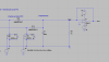
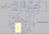
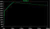
Do you have any experience how to simulate an AC/DC converter with interleaved PFC converter in LTspice? I trying to do that, but I don't get any reasonable values at the output.
I would be so thankful if I could get any advice on how to moving forward from this. The file is also attached if you want to edited it.
 

Attachments

  • forum.png
    forum.png
    29 KB · Views: 1,293
  • forum2.png
    forum2.png
    31.8 KB · Views: 618
  • OBC interleaved PFC NEW.asc
    3.7 KB · Views: 317
You need energy storage (capacitor) at the output of the full wave bridge.
Get rid of the 1N914 (small signal diodes) and replace them with real rectifiers.
To assist in debugging and visualization of how the circuit works, move the ground symbol to the bottom of the output load resistor.
Why do you think you need a 900uF filter capacitor?
 
Yeah, I thought something was missing after the diodes. have now added a capacitor and replaced the small diodes with larger diodes MBR20100CT (10 A). I think the results looks better now, see the attached image.
The reason why I picked 900 uF filter capacitor is because it is part of an vehicle onboard 3.4 kw charger I want to simulate in the end. See the attach image. So at the moment,
I trying to simulate first the AC/DC converter + interleaved PFC first, and then I will trying to simulate the full bridge DC/DC converter. Finally, I hope to simulate these converters together.
 

Attachments

  • forum4.png
    forum4.png
    23.4 KB · Views: 432
  • forum3.png
    forum3.png
    40.4 KB · Views: 522
But, now I had some problems with my DC/DC converters, can you please have a look and let me know what kind of problems can be problematic?
I attached the file here.
 

Attachments

  • OBC interleaved PFC FUNKAR STAGE 2.asc
    5.4 KB · Views: 267
I trying to see if I can get the same waveforms from the interleaved PFC, but it doesnt seems to be the same for some reason. Can you please explain why?
 

Attachments

  • forum1.png
    forum1.png
    57.6 KB · Views: 345
  • forum2.png
    forum2.png
    29.5 KB · Views: 335
  • forum4.png
    forum4.png
    72.5 KB · Views: 375
  • OBC interleaved PFC FUNKAR STAGE 1 (1).asc
    4.3 KB · Views: 216
Try this:
 

Attachments

  • OBC interleaved PFC FUNKAR STAGE ron.asc
    4.4 KB · Views: 275
I want to see if the inductor current from L1 and L2, the input and output voltage, and input current are corresponding to the images.
Because, if they do, it means the circuit works properly. However, I know the scales may not be the same for this so it can be difficult to compare.

It should be operating for single-phase, so I added AC 265 (max. value for this OBC) V 180 degree in the voltage source.
 

Attachments

  • forum1.png
    forum1.png
    57.6 KB · Views: 238
  • forum5.png
    forum5.png
    44.6 KB · Views: 247
  • forum6.png
    forum6.png
    96.1 KB · Views: 259
Aha, I see. Thank you very much, I really appreciate your explanation and help. Just one question about the output voltage from the interleaved PFC circuit, why does the voltage increase? I would like to have it in steady state (stable) at an output voltage of 400 V. Or maybe it will be become stable at some point I guess.

Thanks again.
 
You don't have the PWM working yet. Right now you have a fixed duty cycle and no feedback. There is nothing looking at the 400 volts and keeping it at 400.

Next; PFC 400 volts is not real stable. (there will be some 120hz ripple (100hz in some countries)) The next PWM will remove the ripple.
 
Ah, I see. So some kind of voltage comparator is needed right? So it should look something similar to this? I am not sure if am on the track tough.
 

Attachments

  • forum5.PNG
    forum5.PNG
    25.7 KB · Views: 338
Hi

Just a heads up.....if you want 265 VAC (RMS) input, then the sine wave input amplitude would be 374.7v pk
To verify, show the sine wave by itself, in a separate pane, in the waveform viewer, then Ctl-Lft-Click on the trace label.
It will display the RMS value.

eT
 
So it should look something similar to this?
Linear.com does not have PFC IC so I can not show you how it works easy. (they do have LED bulb PFC but they are not what you are doing)

PFC has a job and it is not to make 400VDC.
PFC is to make a power supply pull current (watts) of the power line just like a resistor.
>>>A resistor has a sine wave in current.
>>>A computer power supply (with out PFC) has a sharp pulse of current at about 20%) No current most of the sine wave.
PFC has a job to pull current in a sine wave.
There are two feed back loops.
>>>1 is very fast. It looks at the input voltage (sine wave) and makes the current match.
>>>2 is a very slow loop. (10hz response time) It tries to make 400VDC.
The end results is that power is pulled off the power line in a sine wave.
BUT
Because the 400hz is "slow" and has low priory, the 400Vdc has ripple and over/under shoots and is not perfect. The next regulator will correct for that.
---edited----
This is not simple. You need to find a PFC IC in LTSpice.
 
Last edited:
I have actually not working so much about IC in general in LTspice, so its quite new for me.
I found two types which could work I believe, but how do I implement them. There is a lot of inputs to these IC, but is everything needed,
or maybe just a few of them?
 

Attachments

  • forum7.png
    forum7.png
    33.7 KB · Views: 255
Attached is a file for the LT1249.
 

Attachments

  • LT1249_TA01_PFC.asc
    5.2 KB · Views: 254
I tried to implement the LT8312, but I am not sure if it reach a stable 400 V. I guess I have made som misstakes when I tried to connect the PFC controller with the AC/DC converter. Could you please maybe identify what could be the issue? I attached the files once again.

Thank you once again,
 

Attachments

  • forum8.png
    forum8.png
    97 KB · Views: 301
  • OBC interleaved PFC + Controller FUNKAR Test 2.asc
    9.8 KB · Views: 217
  • forum9.png
    forum9.png
    28.7 KB · Views: 281
Did you try the circuit from #17?

1. PFC is based on the idea that C1 is very small. You killed any hope of PFC by making C1 large. With C1=300uF you have no PFC but it should boost to 400 volts.
2. You want "interleave". This IC does not do that. Q1 and Q2 are on at the same time.
Interleave = .A.B.A.B.A.
You have this:
....A....A....A....A
....B....B....B....B
3. K1 L1 L2 1 ADD K2 L3 L4 1 You have L3, L4 as separate inductors not a transformer.
4. R3 Why? D11, D12 Why?
upload_2018-3-5_8-44-46.png
 
Last edited:
Status
Not open for further replies.

Latest threads

New Articles From Microcontroller Tips

Back
Top