Continue to Site

Welcome to our site!

Electro Tech is an online community (with over 170,000 members) who enjoy talking about and building electronic circuits, projects and gadgets. To participate you need to register. Registration is free. Click here to register now.

  • Welcome to our site! Electro Tech is an online community (with over 170,000 members) who enjoy talking about and building electronic circuits, projects and gadgets. To participate you need to register. Registration is free. Click here to register now.

Low impedance injector driver - HELP!

Status
Not open for further replies.

1insuare

Member
Hi Everybody,

Thank you in advance for your help, I hope you can help me or give some ideas of how to manage my trouble.

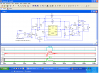
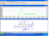
I have to build a low impedance driver. The LM1949 is ideal for this application but I would like to use MOSFETs instead of DARLINGTON transistors to drive the injectors. I am not sure which changes I have to make to achieve a correct working.

Any idea?

Thanks!
 
What are the current and voltage requirements of the injectors?
 
It may be possible to substitute a MOSFET driver for the Darlingtons but why do you want to? The LM1949 is designed to drive Darlingtons.
 
The idea is reduce the power dissipation. I have not found any other peak and hold driver to be used with mosfets. Other problem that I have is that I need to build the circuit in a PCB and there is not LM1949 with SMD package. Would be very difficult to build it with discrete elements? I am trying to do that, but I feel quite lost. Can you help me? Thanks in advance
 
It should be fairly straightforward to add an adapter stage to the output of an LM1949 to drive a MOSFET (I'll see if I can knock up a simulation later today). As for lack of an SMD package you could just bend the legs of the mini-DIP package outwards to make your own SMD version.
 
Thank you for your help mate. Thinking about how to build a circuit with discrete components I came up with the idea of using comparators as appears in the lm1949 datasheet but I don't find the way to implement the output control logic......
 
The idea is reduce the power dissipation. ...................
According to the LM1949 data sheet, the majority of the dissipation occurs during the injector hold mode. That dissipation will be the same whether you use a Darlington or a MOSFET driver. The only dissipation difference would be during the short peak current mode which generates a relatively small amount of dissipation either way. So I don't think a change to a MOSFET driver will create a significant difference in the total transistor power dissipation.
 
I agree with Crutschow (post #9), but if you still want to use a MOSFET instead of a Darlington here's how you could adapt the LM1949 output. D1 is included so that the LM1949 'sees' a simulated Darlington. Q1 and Q2 provide level-conversion. Q3 and Q4 are a push-pull low impedance driver for the FET gate. R5/L1 are an arbitrary model of an injector. D2 reduces the FET turn-off time, at the expense of a rise in the FET drain voltage.
 

Attachments

  • InjectorDriveAdapter.gif
    InjectorDriveAdapter.gif
    15.2 KB · Views: 1,879
Last edited:
Alec, I think the LM1949 operates in linear mode for the hold current so the level shifter might not work.

1Insure, Do you know the dc resistance of the injector? We can maybe make a discrete one.

Also, is the pulse driving it a positive going pulse or negitive going.
 
Last edited:
Alec, I think the LM1949 operates in linear mode for the hold current so the level shifter might not work.
Quite possibly. I am assuming the current sense resistor is used in a negative feedback loop, so the level-shifter would be automatically adjusted to compensate. Not having a model of the LM1949 I can't simulate the whole control loop.
 
That dissipation will be the same whether you use a Darlington or a MOSFET driver.

No, a darlington dissipates more, they make lousy drivers. The reason is a darlington never has less than about .8V drop from collector to emitter, and with any current it's considerably higher. So for a couple of amps, 2A x .8V = 1.6W. Now compare that to a mosfet with .014Ω RDS - .056W. HUGE difference.
 
Now compare that to a mosfet with .014Ω RDS - .056W. HUGE difference.
But the MOSFET only has that low RDSon when it is fully turned on; which it won't be when the driver is providing holding current, i.e. after the solenoid pull-in period.
 
Injector driver

Ahh, I see your problem. The 28 volts makes the power dissipation in the darlington go thru the roof.
Here is a little circuit that might work. The power is still lost but in a resistor instead of the transistor.
In looking closer at the datasheet it looks like the chip can be run in PWM mode (though they don't push it) Have you thought about that option? I'm not sure you can get your ratios between pick and hold -- but.....

The way this circuit works is the positive going pulse from the ECU fires the timer. It is set for about 5 ms (much longer than the time it takes to get to 6 amps). At the same time the hold current is turned on. When the current gets to ~ 6 amps the timer gets reset turning off the "pick" current. The hold current stays on (thru the 5 ohm resistor) until the ECU pulse goes away.
 

Attachments

  • injector driver.PNG
    injector driver.PNG
    76.2 KB · Views: 1,091
Oh, that LM1949's analog instead of PWM. You're right alec_t, sorry crutschow.

OP, you said you have to build "a low impedance driver" and repeated in a subsequent post that you need to reduce power dissipation. If that's the case, you need to use a Pulse Width Modulated (PWM) output injector driver. Here's one, runs mosfets or igbt's, smt style, 4 pwm injector channels (and a spark controller if you want it), in stock at Mouser for $5 -
https://www.electro-tech-online.com/custompdfs/2012/01/MC33810.pdf

Down side is it needs a microcontroller, and if you have one of those you probably don't need this chip because it can do the PWM and drive the mosfet itself. Where are you getting your signal for the injectors?
 
Last edited:
THANK YOU very much for your great help guys. I will try to build a pwm controller and check if this work. I have built my own logic control output using two comparators. Through a senser resistor I measure the voltage and using two comparators (one for the peak current and one for the hold current, this comparator with hysteresis) and some logic gates. I am not sure if this will work... What do you think?
 
Ronv's solution is a good workaround if you just need to relocate the heat. Is the problem that you have limited electrical power on a fuel injected engine that has a 28V supply rail? Might help to give us a little more scope on this thing.
 
Pwm Injector

Here is one that should do it if you don't want a chip. It's getting a little messy> If you can't read it let me know & I'll clean it up.
 

Attachments

  • pwm inj..PNG
    pwm inj..PNG
    77.9 KB · Views: 941
Status
Not open for further replies.

Latest threads

New Articles From Microcontroller Tips

Back
Top