Continue to Site

Welcome to our site!

Electro Tech is an online community (with over 170,000 members) who enjoy talking about and building electronic circuits, projects and gadgets. To participate you need to register. Registration is free. Click here to register now.

  • Welcome to our site! Electro Tech is an online community (with over 170,000 members) who enjoy talking about and building electronic circuits, projects and gadgets. To participate you need to register. Registration is free. Click here to register now.

Low Cost Constant Resistance Electronic Load

Status
Not open for further replies.

GraveYard_Killer

New Member
Hello,

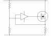
Im about to ask how can I create a constant resistance load using analog components (w/o MCU)...

My current design is capable of constant current using Mosfet + op-amp. But implementing a constant resistance feature looks really difficult. What's going through my mind right now is to create a firmware and do the math processing (I=V/R) to be able to achieve constant resistance.. however, it will be better if there will be no MCU at all...

Thanks in advance...
 
Are you feeling okay GraveYard Killer? If you need a constant resistance you use a resistor of the appropriate value. If you don't want it's value to change much from heating, use a massively over valued power rating.
 
hello Sceadwian,

my target is to have a flexible design.. something which could be set by potentiometers + op-amps, then the Mosfet will take care of the sinking of current in constant resistance mode

also, that is the one problem I want to solve. we are having lots of high wattage resistors of different values...

also, this idea might be enhanced in the future since I may use RS485 network + MCU to be able to set the resistance remotely. that's why I want for it to be controlled electronically...

thanks for the reply.
 
On method I have used for a number of years is to mount the mosfet on a heatsink. From the source to ground use a small value resistor. This resistor is the current sense. The voltage accross the resistor goes to one input of the op amp. The other input to the op amp is from a adjustable regulated supply voltage. The output of the op amp feeds the gate of the mosfet. The drain and ground goes to the supply voltage. The adjustable voltage adjusts the load current. The load current remains constant as the voltage varies. Works great for testing power supplies and discharging batteries.

After rereading the original post, I missread the first time. My design described is in fact a constant current. Sorry Graveyard Killer for the miss understanding the desired result.
 
Last edited:
Any Bipolar or Mos transistor will give approximately constant current for a constant base / gate drive.

You could use a microcontroller to adjust the drive to give constant R, or you could use an op-amp as in the diagram. You can make the resistors on the left a digital potentiometer to give adjustability.

Or you could buy some big resistors and switch them in or out of circuit with mosfets. If you have 3 suitably chosen resistors, that gives you 7 values and open circuit.
 

Attachments

  • virtualr.gif
    virtualr.gif
    5.6 KB · Views: 2,214
thanks for the reply...

my current design works very well on constant current mode... however, what I want to achieve right now is constant resistance...

You could use a microcontroller to adjust the drive to give constant R, or you could use an op-amp as in the diagram. You can make the resistors on the left a digital potentiometer to give adjustability.

yes this is what I did for the constant current.. currently, I don't want to use microcontroller as much as possible... since I know it will really work, I really want to exhaust all possible options first using op-amps or other methods. using MCU will be my last resort.

thanks for the replies
 
how about this? although I'm not sure if I missed the point
 

Attachments

  • variable current load 1.pdf
    68.9 KB · Views: 1,511
Last edited:
I've built a few dummy loads like this, for testing PSU's etc. They are close to "constant resistance" if you dont mind being a few percent out.

Just use a resistive voltage divider with the centre attached to the base of a darlington power transistor and a fixed emiiter resistor to ground.

The volrage on Re will mirror the voltage on Rv but aboiut 1 volt less. If you add one or more diodes in the middle of the voltage divider (like biasing a power amp output stage) you can remove most of the 1v offset.

So a pot, 2 resistor, 1 diode and a darlington will get you within a few percent. :)
 
Last edited:
Killer, what is your application? Is it for power supply testing?
What ranges of voltage, current and resistance do you need?
 
An off-the-shelf "constant current" module that can be configured as a "constant resistance" load (see last page).

https://www.murata-ps.jp/products/power/ds/dtl24a.pdf

Very spendy...~$300

The block diagram and explanation may give you an approach to make a constant resistance load.

Ken
 
Killer, what is your application? Is it for power supply testing?
What ranges of voltage, current and resistance do you need?

yes, it is for power supply testing... I will really be needing a constant resistance in case the output of the supply will be out of regulation in case the PSU is defective... my range of voltage is from 1.2V up to 70V, achieving a power of 250W...

therefore, in case there is a change in voltage, the current should adjust as well (R=V/I).

thanks for the replies

@KMoffett

thanks I will take a look at it..
 
Last edited:
thanks for the reply...

my current design works very well on constant current mode... however, what I want to achieve right now is constant resistance...


yes this is what I did for the constant current.. currently, I don't want to use microcontroller as much as possible... since I know it will really work, I really want to exhaust all possible options first using op-amps or other methods. using MCU will be my last resort.

thanks for the replies

My design, and the one from Mr RB, should be constant resistance. In each case the voltage drop across a fixed resistor, is kept the same as the a fixed fraction of the total voltage.
 
My design, and the one from Mr RB, should be constant resistance. In each case the voltage drop across a fixed resistor, is kept the same as the a fixed fraction of the total voltage.

oh yes... I didn't saw that... the top resistor is attached to the drain and as opposed to constant resistance circuits that the top resistor is attached to a fixed voltage. wow..

I'll do some mathematical computations for that configuration to be able for me to adjust my design for both CC and CR mode...

thanks a lot!!!
 
Last edited:
Hello Diver300,

I verified and it worked.

**broken link removed**

thanks for all those who replied. I appreciated it so much! :)
 
I'm glad to be of assistance.

I noticed that your divider has a ratio of 50% so the circuit effectively doubles the resistance of the physical load resistor.

I would suggest a much bigger ratio, so that less power is dissipated in the resistor and you have a wider range of adjustment. You can't go to less than the physical load resistor in any case.
 
Status
Not open for further replies.

Latest threads

New Articles From Microcontroller Tips

Back
Top