Follow along with the video below to see how to install our site as a web app on your home screen.
Note: This feature may not be available in some browsers.
It looks ok to me, but there are a lot of strange things with the circuit. Maybe it is because I don't know what you want to do. Anyway, it looks like you just want to light an led depending on if the voltage is above or below the threshold voltage while picking a relay above that same threshold?
If that's it I don't see a need for the diodes since you can adjust the threshold (reference) voltage and the hysteresis. It is not a good idea to have U4's hysteresis depend on U1's switching since their offsets may be slightly different. Don't understand the gain for U5 - seems like you just have to adjust the pot lower so you can amplify it back up. The lower comparator can't drive close to ground with the 3 1k's so the relay voltage will be low.
If you want it like I think you do, look at this one.
The ref. pot sets the trip point and the feedback pot the spread. The relay picks above the upper threshold and drops out below the lower threshold. One led on when the relay is on, the other when it is off.
If you use a rail to rail op amp instead of the 358 you can eliminate R5.
A few more parts, but easy to set independent threshold values and will not chatter.
First, have we determined why it is chattering?
Second, this was actually the type of circuit I was hoping for. Independent thresholds and setable at any time independent of the output state. I got so excited by the quick and obvious response, I forgot the other criteria (not to mention I didn't explicit ask for it).
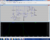
I still need to trace out the current paths to fully understand it, but (having recieved the necessary parts today) I have entered it into my simulator and have it working, My concern with the circuit is how to get the bicolor 2-pin led working. I am attempting to configure two optoisolators to give the opposite polarities I need in order to make it work. Here's my first attempt. I don't think it works yet as the current through R19 (placeholder for the bicolor LED) is 8uA and -6mA.
View attachment 75575
Hi. I do not know why the diode circuit is chattering, but I suspect it has something to do with the diode junction voltage being non-zero, resulting in an inherent dead zone that is larger than the voltage difference between the lower and upper voltage thresholds you are using. Perhaps if you increase the difference between the lower and upper thresholds to something greater than 1.4 volts that circuit will work with that limitation. Perhaps.
I added your bicolor LED driver circuit to the circuit I offered, attached. I do not see a need for optocouplers. The two transistors Q1 and Q2 form a bistable latch so that once a threshold is breached by the input voltage the latch will switch to one state and remain in that state until the other threshold is breached, upon which the latch switches to the other state, and vice-versa.
I added the optocouplers because I did not realize there were or could be two outputs. I hadn't had the chance to trace through the circuit (I still haven't, honey-do list and all). I added your output section but my simulation is howing bouncing in the diode current after the transition. Is that going to be OK?
View attachment 75583
View attachment 75585
Neat circuit ccurtis,
I think ADW said the relay was 240 ma., so it might need a little tweek.
Just out of curiosity did you ever try the large resistor across the diodes to see if that stopped the chatter?
Neat circuit ccurtis,
I think ADW said the relay was 240 ma., so it might need a little tweek.
Just out of curiosity did you ever try the large resistor across the diodes to see if that stopped the chatter?
I added the optocouplers because I did not realize there were or could be two outputs. I hadn't had the chance to trace through the circuit (I still haven't, honey-do list and all). I added your output section but my simulation is howing bouncing in the diode current after the transition. Is that going to be OK?
]
I would like to replace (or add to) the resistors RELAY and R8, optocouplers to isolate the load from the bistable latch. It appears that the resistors in the latch are somewhat dependent on the load. I have another design that may benefit from this design, but I haven't been able to think through that design (as I'm still working on this one).
Where is the relay?