Continue to Site

Welcome to our site!

Electro Tech is an online community (with over 170,000 members) who enjoy talking about and building electronic circuits, projects and gadgets. To participate you need to register. Registration is free. Click here to register now.

  • Welcome to our site! Electro Tech is an online community (with over 170,000 members) who enjoy talking about and building electronic circuits, projects and gadgets. To participate you need to register. Registration is free. Click here to register now.

Looking for compartor circuit with independent threshold adjustments

Status
Not open for further replies.
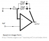
I'm looking for (been looking for) a non-inverting comparator circuit where the adjustments of the hysteresis are independent. I know what the typical (LM393) non-inverting comparator with hysteresis looks like and how it works.

Vth1 = Vref + (Vcc - Vref) *R1 / (R1+ R2 + RL)

Vth2 = Vref - (Vref - VoLow) * R1 / (R1 +R2)

Adjusting either R1 or R2 adjusts both Vth1 and Vth2. I'm looking for a similar circuit where Rx effects only VthLow and Ry effects only VthHi. Any one here know of something that fits the bill?
 
You can connect a diode in series with Rx and Ry to cause each resistor to affect only the high or low reference voltage.
 
dougy83,

The resistors Rx and Ry I mentioned are to fictitious components in the unknown circuit. If your references of Rx and Ry are to R1 and R2 of the original circuit, I was not able to get the desired (or expected) result. I added the diodes in series with R1 and R2. The best arrangement I could find (both forward biased from Vref to Vout), R1 and R2 affected VthLo and neither R1 or R2 affected VthHi (VthHi was only effected by Vref, which also affected VthLo).
 
Here's what I meant. Hope it makes sense. (I also hope that it works)
 

Attachments

  • hyst.png
    hyst.png
    6.7 KB · Views: 190
Last edited:
Vcc becomes (Vcc - 0.7)
Volow becomes (Volow + 0.7)
 
I used 1N914 diodes in the circuit above. I have a few differences. Vref is connected to R1 per the LM393 datasheet and Vin is connected to comparator '-'. I also added a fixed resistor in series with R2b and D2 to help keep the VthHi higher than VthLo.

I have attached the input signal to a 10k pot if I move the pot slowly through the range from VthLo and VthHi the output appears to come "halfway" on. I don't have access to a scope, only a DVM. I don't think it can be "halfway" one, so the output must be chattering? The actual output is a relay and an LED so the "half" output is visually (LED is half brightness) and audibly noticeable (relay is chattering). I'm thinking the output must be bouncing on and off as each of the diodes becoming forward biased then reversed biased and forward biased again. What are your thoughts?
 
If the relay shares the same power rail as the reference and Vin sources, the current through the relay coil can change the ref and Vin voltages. You should decouple the relay and comparator circuits. A bulk capacitor can be used, or an RC filter.

Also, the LM393 has an open-collector output. This means it can only pull low, and cannot drive its output high. Make sure you have an appropriate pullup resistor in place.

If there's still trouble, please post a drawing/schematic of your setup.
 
The LM393 can only sink 6ma, and as pointed out, can source no current. It cannot drive a LED, relay, and the feedback network at the same time....

We are guessing; post your circuit...
 
Last edited:
Working on a schematic bare with me for the moment. That computer isn't working (as well as my truck and wife's car, but that's another story. Only so many hours in a day to fix stuff).

The pull-up is 1K, the high rail is 12V and is the same as the relay but the LM393 does not have enough power to drive the relay directly, so I have a 2N2222A connected to the output with a 1K base resistor to drive the relay (with a kickback diode across the coil).

So to describe it in words for the time being. LM393 output connected to 1K pull-up to +12V. Output/pullup junction is connected to a 1K resistor to the base of 2N2222A. The emitter to ground, and the collector to the relay and diode. High side of relay/diode also connected to +12V.

I am not following on "decouple relay and comparator circuit with a bulk capacitor or RC filter". I have heard of decoupling, but in this case, it would eliminate my base drive and the relay wouldn't work (ie., decoupling by using capacitor in series with base resistor)
 
Stare at this for a while, and tell me why V(out) only pulls up to ~6.3V

Also, With a 1K pull-up, how much current are asking the LM393 to sink?
 

Attachments

  • DF78.jpg
    DF78.jpg
    250.2 KB · Views: 160
Vout only goes to 6.3V due to the 1k-1k-diode resistor divider. And the output is sinking 12mA, about 60% of its 20mA capacity. Where are you headed, Mike?

What I'm seeing with the voltmeter and dougy's circuit, is that in between the hysteresis voltages is a third output voltage (on the DVM). In your circuit it the DVM would probably read in the 3-4V range. Since the output relay is chattering, I'm going to assume (because I don't have a scope to confirm) the output is switching repeatedly and the DVM is displaying an averaged reading.
 
Vout only goes to 6.3V due to the 1k-1k-diode resistor divider. And the output is sinking 12mA, about 60% of its 20mA capacity. Where are you headed, Mike?
He's probably getting at the point that the voltage on the output of the comparator affects the switching points. You could increase the base resistor, or just adjust the setpoints based on the reduced output voltage, if you haven't done so already (I assume you may have as you said that it's working).
 
Vout only goes to 6.3V due to the 1k-1k-diode resistor divider. And the output is sinking 12mA, about 60% of its 20mA capacity. Where are you headed, Mike?

What I'm seeing with the voltmeter and dougy's circuit, is that in between the hysteresis voltages is a third output voltage (on the DVM). In your circuit it the DVM would probably read in the 3-4V range. Since the output relay is chattering, I'm going to assume (because I don't have a scope to confirm) the output is switching repeatedly and the DVM is displaying an averaged reading.

You seemed surprised that the voltage at the output pin was about half supply. The data sheet Im looking at suggests that to get a Vol < 0.25V, the output sink current must be < 4mA. At 10mA, the Vol is > 1.5V

If the output is chattering, then you need to add hysteresis to the comparator's feedback.

I'm not surprised that I get 1/2Vcc for VoutHi. I'm surprised that I can get 0.4V, 4.2V and 6.3V from the output. The input has hysteresis per dougy83 circuit as listed above.

Dougy: How much base drive do you think is needed if I need 240mA on the collector of the added 2N2222a?
 
According to https://www.electro-tech-online.com/custompdfs/2013/08/2n2222.pdf the DC current gain for Ic 150mA out is between 100-300. If it's 100, that would mean you'd need 2.4mA base current for your 240mA load. You can decrease this by adding a transistor (darlington configuration), using a FET or even isolating the base current from the comparator output by using a couple of diodes and a pullup resistor. Or, you can just factor in the actual output voltage when setting up your threshold voltages.
 
If the relay shares the same power rail as the reference and Vin sources, the current through the relay coil can change the ref and Vin voltages. You should decouple the relay and comparator circuits. A bulk capacitor can be used, or an RC filter.

Also, the LM393 has an open-collector output. This means it can only pull low, and cannot drive its output high. Make sure you have an appropriate pullup resistor in place.

If there's still trouble, please post a drawing/schematic of your setup.

To simplify the circuit and in an effort to "decouple" the output section from the feedback section, I increased the comparator pull-up resistor to 2.2k and a series diode of an optocoupler (NTE3098) to the output of the comparator. Careful measurements with two voltmeters shows that when the input voltage is between the thresholds the relay chatters and the LED is half on/brightness. I'm working now strictly with dougy83 schematic with the 2.2k pullup and series optocoupler diode on the output. What the heck is going on? I'm thinking there is something amiss with the diodes and an issue completely biasing the diodes in the feedback circuit.
 
The feedback needs to be from the output to the "+" input. From your description it sounds like it is to the "-".
 
Do you have the same issue with the LED when the relay is removed?
 
Status
Not open for further replies.

Latest threads

New Articles From Microcontroller Tips

Back
Top