Continue to Site

Welcome to our site!

Electro Tech is an online community (with over 170,000 members) who enjoy talking about and building electronic circuits, projects and gadgets. To participate you need to register. Registration is free. Click here to register now.

  • Welcome to our site! Electro Tech is an online community (with over 170,000 members) who enjoy talking about and building electronic circuits, projects and gadgets. To participate you need to register. Registration is free. Click here to register now.

LM3915N-1 Dot/Bar Display Driver

Status
Not open for further replies.

FireAce

New Member
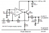
Greetings fellows, I'm trying to do up a circuit with the LM3915N-1 IC to Display audio input for different projects I'm working on, there appears to be many circuits available online, mostly the same schematics but different resistors regarding Pins 6, 7 and 8, something to do with voltage reference.

I have tried many of the different variations of resistors and cannot for the life of me get this circuit to work with proper LED brightness and audio input adjustment via 50k pot. All I'm getting is faint LED performance.

I'm trying to monitor line level or earphone level audio. Below is the link to the circuit.

**broken link removed**

I have a 12v power supply powering both LEDs and IC.

Any ideas?
 
Hi,

I guess the supply voltage you selected is too low for the circuit to be operated.

You might check the circuit using Eric Gibbs' circuit to simulate it perfectly.

Check out the Blogs section for LM3914 circuit. It's quite the same as LM3915, being linear while LM3915 is logarithmic.

Boncuk
 
Are you using a peak detector or sample-and-hold circuit to prolong the input signals to the IC? Raw audio may be changing too rapidly to give a decent visible LED brightness.
 
Pin7 is like the output and pin8 is like the ADJ pin of an LM317 voltage regulator. Then the reference voltage at pin 7 can be any voltage 1.5V less than the supply voltage. When pin6 of an LM3915 is connected to pin7 then that voltage sets the maximum peak input signal voltage that lights the 10th LED.

The datasheet shows that the current to ground out of pin 7 (created by a resistor) sets the LED instantaneous brightness.
Since our vision cannot see a duration less than 30ms brightly then a peak detector is used to extend the duration of momentary peaks.
 
Ok, anyone have a tested and tried peak detector they have PERSONALLY used that works?

I tried the one attached, but replaced the MC33171 opamp with a NE5532, and the results are nothing but lots of noise and LEDS turning full on
 
Ok, anyone have a tested and tried peak detector they have PERSONALLY used that works?

I tried the one attached, but replaced the MC33171 opamp with a NE5532, and the results are nothing but lots of noise and LEDS turning full on
Your attachment is not posted.
My Sound Level Indicator project has a good peak detector that uses an MC34071 opamp that has inputs and an output that go down to ground when there is only a single-polarity supply. It also uses an emitter-follower transistor to ensure that the voltage of the filter capacitor goes to 0.0V when there is no sound and the transistor charges the filter capacitor very quickly.
An LM358 dual opamp can be used instead but has poor high frequency response.

An NE5532 does not have inputs nor an output that goes down to ground so it will not work.
Here is my peak detector circuit:
 

Attachments

  • peak detector.PNG
    peak detector.PNG
    16.2 KB · Views: 582
audioguru, the circuit you attached is exactly the one I was referring to, somehow it failed to attach. Basically your just using a different opamp then the diagram. I will order up the parts and give it a whirl, thanks
 
Status
Not open for further replies.

Latest threads

Back
Top