THANKS !!!!!
Last night was ''play time'' i was changing some resistance values and watching the diagrams
But have a lot of time to achieve something by my self ....
so here i am again with a new question.
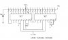
As i told you before the project is to have fuel gauge, oil temp, oil pressure with Lm3914
today was time to see about ''oil pressure''
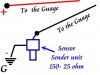
the sending unit gives
20 R = 0 Bar
45 R = 0,5 Bar
60 R = 1 Bar
75 R = 1,5 Bar
95 R = 2 Bar
105 R = 2,5 Bar
125 R = 3 Bar
140 R = 3,5 Bar
160 R = 4 Bar
170 R = 4,5 BAR
180 R = 5 Bar
The problem is that changing R/Bar is not linear
i am not sure if just one lm3914 can display exactly 0,5 - 5 bar
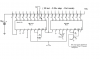
2 lm3914 could work better to display values more accurate to the above readings ?
Last night was ''play time'' i was changing some resistance values and watching the diagrams
But have a lot of time to achieve something by my self ....
so here i am again with a new question.
As i told you before the project is to have fuel gauge, oil temp, oil pressure with Lm3914
today was time to see about ''oil pressure''
the sending unit gives
20 R = 0 Bar
45 R = 0,5 Bar
60 R = 1 Bar
75 R = 1,5 Bar
95 R = 2 Bar
105 R = 2,5 Bar
125 R = 3 Bar
140 R = 3,5 Bar
160 R = 4 Bar
170 R = 4,5 BAR
180 R = 5 Bar
The problem is that changing R/Bar is not linear
i am not sure if just one lm3914 can display exactly 0,5 - 5 bar
2 lm3914 could work better to display values more accurate to the above readings ?
")
")