Ηι
")
It was no volts
My mistake.. i start checking my circuit and i find out that hadnt connect the R7 to the 6V
but still not working as it should ...
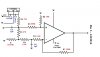
- at the junction of R1 and R2 i have 5.91 volts
but in the output i get 4.66 volts what ever i do - move the floter resistance....
i check it with a 4,7 variable resistance - trimmer instead of the cars floter... i get the same voltage 4.66v out the output for 0 k - 4.7k
what may i have done wrong??
the c1,c2 1μ are 1 μf ? ( that is what i have placed in my circuit)
thanks again both for the interesting you saw to my project-problems


")