Continue to Site

Welcome to our site!

Electro Tech is an online community (with over 170,000 members) who enjoy talking about and building electronic circuits, projects and gadgets. To participate you need to register. Registration is free. Click here to register now.

  • Welcome to our site! Electro Tech is an online community (with over 170,000 members) who enjoy talking about and building electronic circuits, projects and gadgets. To participate you need to register. Registration is free. Click here to register now.

LM386 with electret mic

Status
Not open for further replies.

kerm1t

New Member
Hi everyone,

I'm trying to build one of these things:

https://www.instructables.com/files/orig/FX5/67GS/FLROK12R/FX567GSFLROK12R.gif

LED vu meter, taking it's input from a microphone.

The LM3916 part is working just fine, but I've having problems with the LM386 - the output on pin 5 hardly varies from around 3.7v

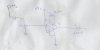
I've tried stripping it down to a very basic amp, as shown in the attachment. If I place the mic an inch from my mouth and hum loudly, I can just about get a swing of 0.4v

Have I just got a really lousy mic, or is there something wrong with my circuit? With that capacitor over pins 1 and 8, I should be seeing a gain of around 200, right?
 
I should be seeing a gain of around 200, right?
That's what the datasheet says:). So your swing of 0.4V implies a mic signal of 2mV. Maybe ok from a dynamic mic, but an electret should give much more.
BTW a peak detector circuit between the 386 and the 3916 would give a more persistent/visible display.
 
Last edited:
Have you tried reversing the leads to the electret? They are polarity sensistive.
 
Thanks for the tip on the peak detector - I'll start researching that next.

I didn't realise electrets has a polarity. This one has no markings on it, and legs on it are both the same length. Still, I've tried reversing it, but no improvement.

Think I'll get an electret from another source and see if it's any better
 
Maybe you have an "un-amplified" electret (low output). Some have a FET preamp built-in. DigiKey has a bunch.
 
Last edited:
An electret mic has its ground pin connected to its metal case.

The LM3916 is connected completely WRONG because Instructables are designed by little kids who can't read (the datasheet).

Pin 8 should be connected directly to ground (not through the 20k resistor R4) for the highest sensitivity.
The brightness of the LEDs is determined by a resistance from pin 7 to ground but there is none. Try 1000 ohms.
R3 and R5 should be wired like a volume control, not like that.
An important supply bypass capacitor is missing. Use 10uf to 100uF from +9V to ground close to the ICs on the circuit board.
 
Whoops, forgot the attachment in my original post. I was a bit skeptical of the instructables schema too, and the attached image was an alternative lm386 wiring that I'd found.
 

Attachments

  • Image (8).jpg
    Image (8).jpg
    28.8 KB · Views: 441
The alternate LM386 wiring is completely WRONG and is completely different from circuits in its datasheet:
1) The ground pin of the electret mic does not connect to ground. Then it connects to the input of the LM386 amplifier and it picks up mains hum.
2) The volume control has the current of the electret mic in it (0.5mA) which biases the input pin of the LM386 to a voltage as high as +5V. But the input pin of an LM386 amplifier is supposed to ALWAYS be 0VDC so the output will be saturated near ground then it will not amplify.
3) The RC zobel network is missing at the output so the amplifier will oscillate at a high frequency.
 
Thanks for your help so far. I'm back on this diagram: https://www.instructables.com/files/orig/FX5/67GS/FLROK12R/FX567GSFLROK12R.gif , (and have noted your comments on the LM3916 wiring). I've also been spending some time reading up on my theory (it's been almost 20 years since I did this stuff at college).

Going back to the mic/lm386 wiring in https://www.instructables.com/files/orig/FX5/67GS/FLROK12R/FX567GSFLROK12R.gif, the signal coming out of the mic should be a steady DC voltage, with an AC wave on top of it. C1 filters out the DC compontent, so just the AC signal goes to the amp, right? My multimeter only handles AC at high voltages (around 200V), but I should still be able to get a reading using the DC setting on either side of C1 shouldn't I? It wouldn't be a reliable value, but I should at least see the value jumping around, indicating that something is happening?

Does C1 need to be bipolar/non-polar? At the moment I'm using a polarized electrolytic (mainly because I didn't have any non-polar to hand). Some sources seems to suggest it doesn't matter, others say you can use two polarized capacitors in parallel, with the polarities the opposite way around to each other
 
C voltage and the input pin
Going back to the mic/lm386 wiring in https://www.instructables.com/files/orig/FX5/67GS/FLROK12R/FX567GSFLROK12R.gif, the signal coming out of the mic should be a steady DC voltage, with an AC wave on top of it. C1 filters out the DC component, so just the AC signal goes to the amp, right? My multimeter only handles AC at high voltages (around 200V), but I should still be able to get a reading using the DC setting on either side of C1 shouldn't I? It wouldn't be a reliable value, but I should at least see the value jumping around, indicating that something is happening?
The output from the mic is tiny, about 0.01V peak at audio frequencies that are too high for a multimeter. A multimeter measures the 50Hz or 60Hz electrical mains frequency, not most audio frequencies.

Does C1 need to be bipolar/non-polar?
The instructables author forgot how to simply calculate the value of the coupling capacitor. 1uF is way too big and a 0.1uF, 0.22uF or 0.33uF film capacitor is fine for audio frequencies to go down very low.
The mic has a positive DC voltage and the input pins 2 and 3 of the LM386 are at 0VDC.
 
Last edited:
Status
Not open for further replies.

Latest threads

New Articles From Microcontroller Tips

Back
Top