Continue to Site

Welcome to our site!

Electro Tech is an online community (with over 170,000 members) who enjoy talking about and building electronic circuits, projects and gadgets. To participate you need to register. Registration is free. Click here to register now.

  • Welcome to our site! Electro Tech is an online community (with over 170,000 members) who enjoy talking about and building electronic circuits, projects and gadgets. To participate you need to register. Registration is free. Click here to register now.

Lm317 battery charger

Status
Not open for further replies.

baxterdmutt

Member
Hi all,
I have been trying to get this battery charger working. I found the schematic on the web and it all looks good (to me) and others claim it works, but for me I can't get the LEDs to work right. The green is supposed to be on while charging and then when the battery is charged (the Zener in reverse bias) redirects the current to the npn transistor through the red led on the way to ground. This is supposed to turn off the green and turn on the red. For me the red comes on when it's charging and the green is always on. Any ideas?
Circuit-Diagram-of-Automatic-Battery-Charger.jpg
 
I see nothing in this circuit that would turn off the Grn LED. It is simply a pilot indicating that there is voltage at pin 2 of U1.

Here is a sim. Note when V(bat1) reaches~14V, the red Led turns on I(D3), but the green LED I(D4) is always on.

In this circuit, R1 does nothing. The LM317 provides only thermal current limiting, it is not doing any regulation. The cutoff voltage is the sum of the forward drop across the 11V Zener + Vbe + Vf of the red LED, very imprecise, and very temperature dependent. Not adjustable. Overall, a poor circuit, typical of the stuff found on the Web.

hu3.png
 
Last edited:
D6 might be backwards?
Recheck the E,B,C on Q1. You might have the transistor backwards.
Measure the voltage across D6. Is it 0.7V or some thing about 10V?

------------edited-----------
It looks like the charger "shuts off" after the battery is charged. This will greatly reduce the voltage to the green LED.

What voltage of battery are you charging?
 
In this circuit, R1 does nothing. The LM317 provides only thermal current limiting, it is not doing any regulation.
It will regulate voltage if you use the original value of 1kΩ for R1 and adjust the pot RV1 to around 1.4kΩ
 
It will regulate voltage if you use the original value of 1kΩ for R1 and adjust the pot RV1 to around 1.4kΩ
I tried 5K to 11K, and that didn't effect the operation. If you use RV1 < 1.4K, then you will reduce the final battery voltage, but then the Red LED will never come on...
 
I tried 5K to 11K, and that didn't effect the operation. If you use RV1 < 1.4K, then you will reduce the final battery voltage, but then the Red LED will never come on...
It regulates fine. In fact with the exception of the 2 LEDs the transistor and the Zener, it's right out of the lm317 datasheet. The red light comes on when it's charging as well as the green. I did check the pins on the transistor and they are the right way around.
 
POST ISSUE 04 of 2016_12_22

Hi BM,

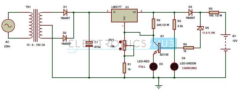
Interesting battery charger.

As Mike says in post #2, the circuit is pretty imprecise and there appears to be no way that the green LED will ever turn off.

The circuit has two operating modes when a battery is connected (assuming a 12V lead acid battery is being charged):
(1) Charging, where the transistor, Q1, is off and the charge current is defined by the voltage on the left of R5 and the voltage on the right of R5. In this mode the Zener diode, D3, will be non-conducting and the transistor, Q1, will be off. So the voltage on the left of R5 is set by the LM317 via the 1N4007 diode, D5.
(2) Not charging, where Zener diode, D3, is conducting and there is a feedback loop which stabilizes the voltage at the left of R5 to, red LED, D3, forward voltage (1.6V roughly) + transistor, Q1, Vbe (0.6V) + Zener diode, D6 Vr (11V) = roughly 13.2V.

Some thoughts:
(1) Green LED D4 can never turn off.
(2) The circuit will probably not fully charge a 12V lead acid battery. The float voltage is not well defined but would be around 13.2V rather than 14.1V
(3) The circuit has no decoupling capacitors so the LM317 is liable to oscillate.
(4) The minimum load current of 10 mA for an LM317 is not necessarily provided under all circuit conditions.
(5) There is no allowance in the design for leakage currents, especially in the Zener diode.
(6) I am intrigued to know why a BD139 medium power transistor is specified, rather than a small signal transistor.
(7) R1 does nothing.
(8) If the output is shorted to 0V, R5 will fry
(9) The battery charge current is not well defined

Solutions
(1) No simple/reliable solution at the moment.
(2) Fit a potentiometer to set the float voltage.
(3) Connect a 220nF disk ceramic capacitor from the input pin of the LM317 to the ADJ pin of the LM317. Connect a 220nF disk ceramic capacitor from the output pin of the LM317 to the ADJ pin of the LM317.
(4) Change R2 to 120R. (in theory, the 10K variable resistor should be changed to 5K).
(5) Connect a 10K resistor from Zener diode, D6 lower, to 0V.
(6) Fit a small signal transistor in place of the BD139: BC546 etc
(7) Remove R1 and replace with a wire link (or leave R1 in circuit- it makes no difference)
(8) Make R5 at least 3W power rating.
(9) No simple/reliable solution at the moment.

Just for reference:
https://www.electronicshub.org/automatic-battery-charger-circuit/
https://www.st.com/content/ccc/reso...df/jcr:content/translations/en.CD00001225.pdf
https://www.ti.com/lit/ds/symlink/lm317.pdf
https://www.fairchildsemi.com/datasheets/BC/BC546.pdf
12V lead acid battery voltages
(1) Nominal: 12.6V (2.25V per cell)
(2) Minimum discharge voltage: 10.5V (1.75V per cell)
(3) Maximum charge voltage 14.10V (2.35V per cell): good balance between battery life and capacity.

spec
 
Last edited:
POST ISSUE 03 of 2016_12_28 The transistor circuit is incorrectly drawn. Please see later revised schematic in POST #49

Hi again BM,

Below is a circuit I did for an LM317 battery charger for you to look at. It has reasonably accurate current and voltage control.
There is no 'Charge Complete' indicator, but when the red 'CHARGE' LED extinguishes, the battery is charged.

There is also a green 'POWER ON' LED.

spec

2016_12_22_Iss1_ETO_LM317_LEAD_ACID_BATTERY_CHARGER_V2.jpg
 
Last edited:
Spec,
Glad to see you removed the "R5 100 ohm 1/2w" resistor". Before it was inside the feed back loop. (from post #1)
I thought about moving your "120R" so it see the battery voltage direct. (post #8)
The 1N4007 could be any part in that family. 1N4002 is fine.

Looks good. With the red LED on it charges at constant current mode. Then with the red LED off it charges at constant voltage mode.

Many years ago I made some thing like this. I did not have a large cap on the full wave bridge. So there was much ripple. (0 to 20V) The battery engineer said he liked the idea of 120hz pulses slightly better than charging with dc. The charger was much smaller with out the cap. "Any thing to save $." lol It does make trouble shooting harder.
 
  • Like
Reactions: jjw
Spec,
Glad to see you removed the "R5 100 ohm 1/2w" resistor". Before it was inside the feed back loop. (from post #1)
I thought about moving your "120R" so it see the battery voltage direct. (post #8)
The 1N4007 could be any part in that family. 1N4002 is fine.

Looks good. With the red LED on it charges at constant current mode. Then with the red LED off it charges at constant voltage mode.

Many years ago I made some thing like this. I did not have a large cap on the full wave bridge. So there was much ripple. (0 to 20V) The battery engineer said he liked the idea of 120hz pulses slightly better than charging with dc. The charger was much smaller with out the cap. "Any thing to save $." lol It does make trouble shooting harder.

Hy Ron,

I couldn't resist having a go at this one. Using an LM317 for battery charging is always a challenge.

The original circuit was quite interesting- did you read the write-up on the original site?

Yeah, I considered sensing the battery voltage direct, but in the end thought an 1N400x outside the voltage control loop wouldn't do too much harm.

Eliminating a reservoir capacitor on your PSU design is a big size, cost, and reliability benefit.:)

spec
 
Last edited:
POST ISSUE 02 of 2016_12_22

Hi again BM,

Below is a circuit I did for an LM317 battery charger for you to look at. It has reasonably accurate current and voltage control.
There is no 'Charge Complete' indicator, but when the red 'CHARGE' LED extinguishes, the battery is charged.

There is also a green 'POWER ON' LED.

spec

Thanks again Spec,
I'll give this a try. I have some 12 and 6v batteries and the plan was to adjust the 12v charger (once I got it working) down to a 6V charger. I don't see that as a problem on your design unless I'm missing something. As far as the one I got from the internet goes, I think R1 was there just to keep the sense resistance at at least 1k. I wasn't using on the breadboard since it didn't seem needed. I now realize that the red LED is on when charging and not when complete because the Zener goes into reverse bias as soon as the voltage is high enough to charge so could never work like it was designed to. I did not have any trouble bringing the charge voltage up to over 14 volts and it does charge the battery. Except for the 1n4007, everything to the right of the schematic is useless! Well, that's not completely true, the LED emits, so I can tell the circuit is on:confused:
Hi BM,

no sweat.

I think the circuit will adjust down to suit a 6V lead acid battery. Just set the charge voltage to 7.05V and you are done.

The current limit, with the current limit potentiometer set to zero Ohms is 0.6V/33 Ohms = 18mA and increases as the current limit potentiometer resistance increases.

I hope the circuit works OK

spec
 
Just a quick update;
The charger I gave the schematic for will work as advertised if the cathode of D6 is on the other side of R5 (closer to the battery). I imagine R4 would act as the Zener's current limiting resistor. Of course it probably still has the same deficiencies that have been pointed out, but at least I got it to work.
 
Spec,
What is the purpose of the 220nf caps on the input and output of the lm317 on your schematic? Is it just for ripple or is there another reason?
 
Hi BM,
spec has answered this question in post #7 Under point 3 of "Some thoughts" he points out the lack of decoupling capacitors which are required to prevent oscillation. Almost all voltage regulators require decoupling in the input and output terminals. The capacitors should be mounted as close as possible to the pins on the regulator IC.

Les.
 
I tried 5K to 11K, and that didn't effect the operation. If you use RV1 < 1.4K, then you will reduce the final battery voltage, but then the Red LED will never come on...
Good point.
 
Yeah, I considered sensing the battery voltage direct, but in the end thought an 1N400x outside the voltage control loop wouldn't do too much harm.
If you sense the batter directly; if the power fails, then there is a load on the batter. The sensing current will be out of the battery. A battery charger should not discharge the battery, when 110/220 fails. So you are right with your design.
 
If you sense the batter directly; if the power fails, then there is a load on the batter. The sensing current will be out of the battery. A battery charger should not discharge the battery, when 110/220 fails. So you are right with your design.
Thanks Ron,

I did a MOSFET reverse protector too, which had effectively no intrusion, but it seemed over the top for an essentially simple circuit.

spec
 
This discussion got me to thinking about a (sorta smart) LM317 lead-acid 12V battery charger that would drop to a trickle charge voltage when the battery is charged, so below is my take on that.
It charges at a high voltage (around 14.5V) with a current limit and then, when the current drops to a low level indicating its charged, the voltage is reduced to a trickle-charge voltage (about 13.5V depending upon the type of battery).

An LM339 quad comparator is used to provide current limit, end of charge detection, and control an LED charge indicator.

U7 controls the maximum current by monitoring the voltage across shunt resistor R5, with the limit value determined by the CL voltage from R4 and R9 connected to the 2.5V U3 reference voltage.
The current-limit value can be changed by using a different value for R4.
C3 provides loop compensation when in the constant-current charge mode.

U2 determines when the charging current has dropped below a level set by resistors R7 and R8 (≈200mA for values shown). That causes U2's open-collector output to short U5 to ground, reducing the LM317's voltage set point.
The fast-charge and trickle-charge voltages are determined by the settings of pots U4 and U5.

U6 turns the charging LED ON when it detects charging current across R5, and OFF when the circuit goes to the trickle-charge mode.

The LTspice simulation shows a charge voltage of ≈14.5V and trickle voltage of ≈13.5V for the pot settings shown.
It charges at ≈1A for the given values of R4, R9 and then goes to the trickle voltage when the current drops to ≈200mA.
The battery voltage [V(Out,1)] then will slowly drop to 13.5V, at which point the low trickle charge current will start (current value determined by the battery characteristics, which here is determined by the value of Rp in the simulated battery).

Any thoughts, comments on this design?

upload_2016-12-27_10-17-21.png
 

Attachments

  • LM317 Bat Chg with Float.asc
    5.7 KB · Views: 185
Last edited:
Very neat Cruts- I like the way you have used the open collector of the LM339.

spec
 
Status
Not open for further replies.

Latest threads

New Articles From Microcontroller Tips

Back
Top