Electro Tech is an online community (with over 170,000 members) who enjoy talking about and building electronic circuits, projects and gadgets. To participate you need to register. Registration is free. Click here to register now.
Welcome to our site! Electro Tech is an online community (with over 170,000 members) who enjoy talking about and building electronic circuits, projects and gadgets. To participate you need to register. Registration is free. Click here to register now.
Hey no problem, just rewire your transistor and you're all set right?
Here's a drawing showing the transistor emitter a little clearer.
Oh but i am not sure if you want that diode in series with the battery for an Li-ion as that messes up the voltage regulation a little. It's up to you though.
Hi again Spec,
As long as 33R is connected I get no output and the red led does not turn on (ever). If I pull 33R then I can adjust the output current (it won't go down low enough without a change. Not able to go below 80ma and my battery only need 12ma. ) and the red led is on when not charging.
Hi again Spec,
As long as 33R is connected I get no output and the red led does not turn on (ever). If I pull 33R then I can adjust the output current (it won't go down low enough without a change. Not able to go below 80ma and my battery only need 12ma. ) and the red led is on when not charging.
You are correct about the undesirability of the diode in series with the output but, on balance, it should be OK for a lead acid battery, which is the target application.
But even so, the voltage effect of the diode is not that great.
Below is the corrected circuit for the LM723 battery charger.
spec
NOTES
(1) LED 1 needs to be a very high efficiency type (714uA)
(2) To set the charger up for a 12V, nominal, lead-acid battery, set RV2 (CURRENT) to maximum resistance. Connect a 1K resistor across the charger output terminals (no battery connected) and adjust RV1 (VOLTAGE) for an output voltage of 14.1V
(3) For an output voltage of 14.1V, RV1 (VOLTAGE) will be set to around 1.34K
(4) There will be a standing current of 10.42 mA flowing through the current sense resistors (RV2 + R4) by virtue of the 120 Ohm resistor connected between the LM317 OUTPUT and ADJUST terminals (1.25V). This standing current through the current sense resistors (RV2 + R4) will drop by around 714uA when current limiting is active.
(5) Decoupling capacitors, C1 and C2, should be disc, +-10% disc ceramic types with an X7R dielectric.
(6) C3 should be a high ripple current, low ESR capacitor intended for reservoir applications. The dielectric can be aluminum or polymer.
Hi all,
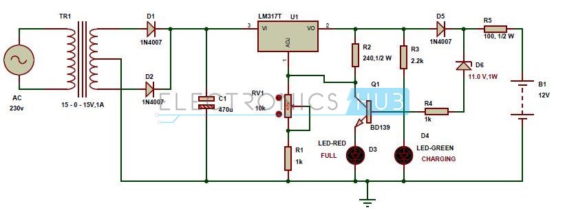
I have been trying to get this battery charger working. I found the schematic on the web and it all looks good (to me) and others claim it works, but for me I can't get the LEDs to work right. The green is supposed to be on while charging and then when the battery is charged (the Zener in reverse bias) redirects the current to the npn transistor through the red led on the way to ground. This is supposed to turn off the green and turn on the red. For me the red comes on when it's charging and the green is always on. Any ideas?
Fully agree Ron.That is one of the fundamental tenants of a good schematic, and if I had followed it, the error with the transistor would have stood out like a sore thumb. But that does not mean that I would not still have missed it.
My excuse is incompetence, lack of focus, and complacency- the LM317 charger is such a simple circuit that I dashed it out without really paying attention.
Getting back to schematic layouts, I have been thinking for years about doing a guide, but never seem to get around to it- perhaps, in abridged form, a suitable topic for an ETO article. I broached this subject with Matt about ten months ago: Matt has already done some work on schematic good practice.
On the whole, the schematics on ETO are easy to follow, as are the technical descriptions, and both are well above the average that you see in some areas, although a few newbee posts make me smile because it brings back memories of the days when I could not follow a circuit but would have loved to.
This site uses cookies to help personalise content, tailor your experience and to keep you logged in if you register.
By continuing to use this site, you are consenting to our use of cookies.


")