Continue to Site

Welcome to our site!

Electro Tech is an online community (with over 170,000 members) who enjoy talking about and building electronic circuits, projects and gadgets. To participate you need to register. Registration is free. Click here to register now.

  • Welcome to our site! Electro Tech is an online community (with over 170,000 members) who enjoy talking about and building electronic circuits, projects and gadgets. To participate you need to register. Registration is free. Click here to register now.

Battery Charger Circuit

Status
Not open for further replies.
Hello everyone.

I have a 24 volt charger from an Ortho-Kinetics Triumph scooter, that I'm trying to use to charge 2 12v batteries in series.

The charger plug has 2 large pins which I assume are for the main charging current,

and 2 smaller pins, which I suspect are for some sort of interlock or charge rate control circuit.

The charger will only put out 22.5 volts at a low amperage, from the 2 large pins, when connected to the batteries. I don't want to do the wrong thing playing with the 2 smaller pins, and risk blowing the charger out. Does anyone know what the 2 smaller pins need to be connected to?

Any help greatly appreciated.
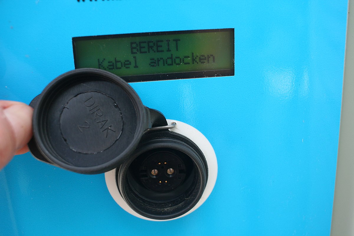
 
The charger will only put out 22.5 volts at a low amperage
That's not enough to charge a 24V lead-acid battery.
You need at least 29V.

The smaller pins may be to detect the battery voltage while avoiding the voltage drop in the cables carrying the charge current.
Not connecting those may be why the charger output voltage is low.
 
Is it an ROPD connector like this here?

That's the only mobility scooter charge connector I can find, that has two large pins plus smaller pins.

With those, two small pins are apparently a CAN bus data link, not just voltage monitoring or logic control.


If that is the case, then the charger is probably operating in some kind of battery recovery mode, giving just enough power to revive dead flat batteries & get the electronics in the scooter powered up and communicating - which won't happen without the scooter side control system connected.
 
Can you determine where the two smaller connections go in the scooter?
 
Hello everyone.

I have a 24 volt charger from an Ortho-Kinetics Triumph scooter, that I'm trying to use to charge 2 12v batteries in series.

The charger plug has 2 large pins which I assume are for the main charging current,

and 2 smaller pins, which I suspect are for some sort of interlock or charge rate control circuit.

The charger will only put out 22.5 volts at a low amperage, from the 2 large pins, when connected to the batteries. I don't want to do the wrong thing playing with the 2 smaller pins, and risk blowing the charger out. Does anyone know what the 2 smaller pins need to be connected to?

Any help greatly appreciated.

Hi,

Any guesswork here would most likely cause a big problem. When it comes to charging batteries you can't mess around too much or things get really bad. Even lead acid batteries can blow up, and when they do they spew plastic and acid all over the place. Not something you want to have happen.

The only real way to know what is going on is to contact the manufacturer. They would know what they are for. There is another way, but it involves a lot of tedious work. You can trace out the PC board and draw a schematic. I've done this many times in the past and it works. If the parts are common, you can troubleshoot the entire circuit and find out if something is wrong as well as find out what the input/output connections do.

You are right in not connecting anything yet at the very least you could blow out the PC board and that would just make things worse.

I could give you some experiments to try but they would have to be done very very carefully so I do not thing it would be wise.

As another reader suggested, the battery voltage to charge a battery has to be quite a bit higher than the nominal voltage. If you have a 12v battery, even the float charge is as high as 13.9v, and for two batteries in series that's already 27.8 volts which your output is not even close to yet.
However, there could be a problem with the batteries causing this also. You'd also have to test the batteries first.

Finally, charging two lead acid batteries in series is not really that great of an idea anyway. How do you control the voltage for each battery when the impedance of each one could vary wildly. The correct charge voltage to start would be at least 28 volts, and what if one gets 16v and the other gets 12v, that means only one charges. As they charge the apparent impedance gets higher or lower, and I do not think you can control the charge from just measuring the voltage across both batteries. Temperature differences between the two batteries is also an issue. You'd have to have a sense input for BOTH batteries. That's the right way to do it. That way the circuit knows the charge state of both batteries and can adjust the output to both batteries at the same time.

When it comes to charging batteries I always tell people to do it right. You can mess around with NiCd or NiMH cells but not with lead acid or lithium based cells. Very different. Why mess around anyway. If you want to charge them, you want them to charge the right way so they charge correctly and also have the life that they were designed to have.
 
Hi,

Any guesswork here would most likely cause a big problem. When it comes to charging batteries you can't mess around too much or things get really bad. Even lead acid batteries can blow up, and when they do they spew plastic and acid all over the place. Not something you want to have happen.

The only real way to know what is going on is to contact the manufacturer. They would know what they are for. There is another way, but it involves a lot of tedious work. You can trace out the PC board and draw a schematic. I've done this many times in the past and it works. If the parts are common, you can troubleshoot the entire circuit and find out if something is wrong as well as find out what the input/output connections do.

You are right in not connecting anything yet at the very least you could blow out the PC board and that would just make things worse.

I could give you some experiments to try but they would have to be done very very carefully so I do not thing it would be wise.

As another reader suggested, the battery voltage to charge a battery has to be quite a bit higher than the nominal voltage. If you have a 12v battery of electric scooter, even the float charge is as high as 13.9v, and for two batteries in series that's already 27.8 volts which your output is not even close to yet.
However, there could be a problem with the batteries causing this also. You'd also have to test the batteries first.

Finally, charging two lead acid batteries in series is not really that great of an idea anyway. How do you control the voltage for each battery when the impedance of each one could vary wildly. The correct charge voltage to start would be at least 28 volts, and what if one gets 16v and the other gets 12v, that means only one charges. As they charge the apparent impedance gets higher or lower, and I do not think you can control the charge from just measuring the voltage across both batteries. Temperature differences between the two batteries is also an issue. You'd have to have a sense input for BOTH batteries. That's the right way to do it. That way the circuit knows the charge state of both batteries and can adjust the output to both batteries at the same time.

When it comes to charging batteries I always tell people to do it right. You can mess around with NiCd or NiMH cells but not with lead acid or lithium based cells. Very different. Why mess around anyway. If you want to charge them, you want them to charge the right way so they charge correctly and also have the life that they were designed to have.
thank you so much for your suggestion
 
thank you so much for your suggestion

Hello again,

You are very welcome.

I should also mention that I have charged single batteries in the past by monitoring the voltage and the current minute by minute by setting a timer and checking the values manually with two meters set up to constantly measure the values. This is not that bad of an idea but you do have to watch those meters at least once every minute. That way you avoid overcharging as that is one of the main causes of battery explosions and fires. Charging is the most risky procedure that's why good chargers are always recommended.

I suppose you could do that with two batteries in series, and get ready to shut off the current once one battery gets too high in voltage, and make sure the current does not exceed any one of the battery's max charge current levels. You do have to be careful though because if you get distracted and forget to check the values for a longer time it could be a disaster.

The problem here is that this is a very tedious operation, and you could get tired of checking the readings halfway though when the charge time might be as long as 8 hours.

There is some instrumentation you can use to monitor batteries in series or parallel. I had created a hardward measuring device a long time ago and provided the software to go with it. That set off an alarm when one of the readings exceeded whatever you set in the software. That would alert you right away that one of the batteries was getting too high. I created that because I got tired of monitoring meters manually.
I created a special chip to do this but I only sold them as a kit not a completed unit. There were some resistors and opto coupler and stuff that went with the chip in the kit. I haven't made one of these in a long time though, and the setup for any charging takes a little thought too.

Now I use a good charger I purchased online some time ago. It does almost everything I need. That's usually the best bet because it involves a lot less work :)
 
Using a multimeter, carefully measure the voltage on the smaller pins when the charger is connected to the batteries. This may give you a clue about their function. Be cautious and ensure you don’t short any connections.
 
Dead threat, that user no longer exists.

The question is a copy of one posted years ago on another site, as were others by the same person.
 
Status
Not open for further replies.

Latest threads

New Articles From Microcontroller Tips

Back
Top