Continue to Site

Welcome to our site!

Electro Tech is an online community (with over 170,000 members) who enjoy talking about and building electronic circuits, projects and gadgets. To participate you need to register. Registration is free. Click here to register now.

  • Welcome to our site! Electro Tech is an online community (with over 170,000 members) who enjoy talking about and building electronic circuits, projects and gadgets. To participate you need to register. Registration is free. Click here to register now.

12v battery, 18v magic

TinkerPhil

New Member
I bought an 18v mower with no battery.
Maybe naively I thought I'd be able to run it off a 12V battery charger but no... Nothing!

So I checked all the circuits and they're good weirdly though the 12v input from the charger measured at 18v as if the circuit was so eager for 18v it was forcing 18v back to the source.
When I took the source away the 18v slowly dwindled down

I'm guessing there's some sort of boost circuit in the mower that needs a healthy 18v source to actually power the mower

Now I carelessly ran 12v the wrong way into the circuit - will I have fried it?

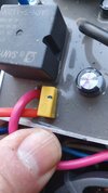
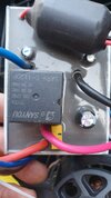
so here's a picture of the circuit in the mower

Can anyone give any quidance?

Thanks
 

Attachments

  • 20250521_201739.jpg
    20250521_201739.jpg
    813.3 KB · Views: 99
  • 20250521_201731.jpg
    20250521_201731.jpg
    1,023.5 KB · Views: 99
An 18 V battery mower will almost always cut off at some voltage to protect the battery, and I would expect that voltage to be somewhere around 14 to 16 V.

A 12 V battery charger will often put out 18 V with no load. Chargers designed to connect directly to a battery are unlikely to be suitable to run anything directly.

The current that the mower will take, especially when starting, will be quite big and you would need a very large power supply to run it.

Connecting a power supply backwards may have damaged something but without a lot more information it's hard to know for sure.
 
Thanks for the reply

It was actually a car battery I wired in the wrong way round - doh!

I suspect it is fried

but I will try to wire it up with an 18v source and see where that takes me
 
Thanks for the reply

It was actually a car battery I wired in the wrong way round - doh!

I suspect it is fried

but I will try to wire it up with an 18v source and see where that takes me

The proper battery will be Li-Ion (and almost certainly 18650's) - and will be 5 in series (or more than one set of five, in parallel for higher capacity) - personally I'd call it a 21V battery pack, as when fully charged it will read 21V (5 x 4.2V). The 18V figure is when they are flat, 5 x 3.6V = 18V.
 
Yeah, I was hoping to avoid having to get a converter for my other "18V" batteries and just whack a car battery on it and use it for hours

seems like I will have to go the extra mile and use the proper voltage/capacity batteries

hopefully I've not fried it!
 
In my defence this basic battery charger drove my 18v circular saw ok

and I did the original frying using a car battery :-(

I don't believe the charger really wants to pump out 18v, I reckon the driven circuit is somehow raising the voltage itself

there must be some capacitors in there as the voltage tailed off slowly when I removed the charger - hence the "magic"

My question (other than have I fried it) was really are there circuits that take a varying load in and regulate that input to a standard value.

LOL I'm really no good at phrasing this question sorry!

There's no 'magic', it runs off a 21V (18V when flat) Li-Ion battery, they may a capacitor inside?, but not a very big one, so it wouldn't 'tail off slowly' if was working.

BTW, you even show a (small) capacitor in your pictures.
 
Apologies, the word 'magic' is obviously irritating - I just did not have the words for it

My charger is a very simple one its just a transformer which drops the voltage to 13.3V and a meaty bridge rectifier - there is no way it is pumping out 17v

so the 17v is somehow coming from the circuit - undoubtedly using the one or more of the exposed capacitors

but this seems entirely moot as I gave it 20v yesterday and it did nothing

There are only 2 wires coming from the battery and I doubt the battery has anything smart in it (though that might explain why they cost nearly £100) so I think I must have fried it :-(

Haha I did check the wiring but still hooked it up wrong!


Anyway, looking at the circuit, I see some capacitors and a meaty solenoid which is supposedly driven off 12v


I believe the solenoid is connected to the switches on the handle and simply pass the meaty output from the battery into the motor The whole circuit looks like its been epoxied to a heat sink but I'm unsure there are any beefy triacs etc to power the motor so I think I might have fried the circuit that provides the 12v needed to switch the solenoid (and that circuit might have voltage regulator which needs a heatsink)


Does the above sound likely?
 
Ha! How wrong can I be?

Very!

I removed the epoxy - actually some sort of waterproofing silicone and I found a very intricate circuit20250523_125503.jpg

with at least two triacs attached to the heat sink :)

As to whether I have the skills or patience to fix it is another matter

I don't

and so I likely won't


Perhaps I will look for a 20v battery motor driver (that has a switch to turn it all on/off)
 
Apologies, the word 'magic' is obviously irritating - I just did not have the words for it

My charger is a very simple one its just a transformer which drops the voltage to 13.3V and a meaty bridge rectifier - there is no way it is pumping out 17v

so the 17v is somehow coming from the circuit - undoubtedly using the one or more of the exposed capacitors
Cheap battery chargers will often have no smoothing capacitor. The peak voltage may be as much as 17 V but the average voltage will be just 13.3 V. Any reasonably large capacitor connected to the output of the charger with no othe load would cause the voltage to rise to 17 V
 
with at least two triacs attached to the heat sink :)
I would imagine they are more likely to be FET's than TRIAC's, there's an obvious big relay on the board, possibly that switches power to the motor, and only does so when the battery is working properly?. Wit Li-Ion batteries there's usually a complicated charging and protection routine involved.
 
Looking at the tracks on the board it looks like the relay is just a final on/off overide driven by the switch on the handle

maybe the speed of the motor is handled by the FETs/TRIACs perhaps using PWM?

I guess it'll need that sort of control to stop it spinning infinitely fast and flinging the blade out

The battery has a separate charger and only 2 wires come from it so I'm not entirely sure why it has such a complicated circuit in it - it seems overkill

The 50 amp capacity of the relay suggests that I'd need a similarly capable motor controller - shame as the 30A ones are less than a tenner
 
The battery has a separate charger and only 2 wires come from it so I'm not entirely sure why it has such a complicated circuit in it - it seems overkill

It's almost certainly NOT a charger, just a power supply, the 'charger' circuit is usually local to the battery - charging Li-Ion batteries is complicated and important (or they set on fire), and particularly if you're trying to fast charge. Not something you really want to try and do remotely over just a pair of high current wires.

The circuit could also easily contain a speed control, not to stop it "spinning infinitely fast", which wouldn't happen anyway, but to maintain a fixed speed independent of the battery charge level.
 
The 50 amp capacity of the relay suggests that I'd need a similarly capable motor controller - shame as the 30A ones are less than a tenner
The 50A relay current capacity is standard with the auto relay model. There's no heatsink for the current/ voltage regulator on the PCB and it's not a switching PSU. Fault diagnosis should be straightforward.
 

Latest threads

Back
Top