Continue to Site

Welcome to our site!

Electro Tech is an online community (with over 170,000 members) who enjoy talking about and building electronic circuits, projects and gadgets. To participate you need to register. Registration is free. Click here to register now.

  • Welcome to our site! Electro Tech is an online community (with over 170,000 members) who enjoy talking about and building electronic circuits, projects and gadgets. To participate you need to register. Registration is free. Click here to register now.

LED flasher does not work need help.

Status
Not open for further replies.
Most of my solar garden lights use an RGB LED that changes its colors. The circuit that powers them steps up the 1.2V from an AAA Ni-MH rechargeable cell and limits the current. I never tried blowing one up by connecting directly to a battery.

Since the maximum allowed voltage of the Chinese LEDs is only 3.6V then they probably need a series current-limiting resistor and will not light up with a 3V battery that drops to 2V.

OK so an LED won't light up on 1 battery. It won't light up with 2 batteries. 3 batteries will smoke the LED. What about the LED flasher I built with Chinese bargan pack of LEDs it runs on 2 AA batteries from Harbor Freight meter shows each battery voltage 1.4v x 2 = 2.8v total. But wait, better batteries will be about 1.6v x 2 = 3.2v LED lights up on 2 batteries. 3 batteries will be close to 4.5v.

Auto blinker LED must be a different voltage.

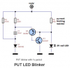
If I want a single Red LED blinker I need to build this circuit. I don't believe 9v is correct my other circuit said 9v I tested with with 1 battery then 2 batteries. Wait a minutes I can't build this I don't have these transistors.

**broken link removed**
 
Last edited:
There are hundreds of transistors almost the same as BC557 and BC547. But your circuit will blow up the LED because it does not have a series current-limiting resistor like your other circuit will blow up the LED with three 1.5V batteries, because it is also missing a series current-limiting resistor.

I made circuits something like that 45 years ago where the two transistors are in one package called a PUT. Look at PUT LED Flasher Circuits in Google.
Some circuits by students on the other side of the world DO NOT WORK. Here is a circuit that probably works:
 

Attachments

  • PUT LED blinker.png
    PUT LED blinker.png
    66.7 KB · Views: 531
The red might burn out if you power it directly from a 3V battery.

A CR2032 battery is rated for 0.19mA but might be able to provide 20mA for a few minutes with its voltage dropped to 2.7V. Soon its voltage will drop to 2.3V when overloaded with 10mA.

Others who have done this have had much more success than your comments suggest. Attaching LEDs directly across 2032 cells isn't my idea. Check out this article on LED Throwies.
 
A Throwie is a great way to throw money away. CR2032 batteries are sold at Walmart for $2.00 US each. Some of them dimly light an LED for a couple of hours, getting dimmer and dimmer as the battery runs down.

I made some LED Chasers that are very bright for 3 months. Red ones use two AA alkaline batteries ($1.00 US) and multi-colored ones use four AA alkaline batteries ($3.50 US).

You have to buy in bulk (and possibly questionable sellers selling possibly counterfeit batteries) to get the good deals on CR2032 batteries.

https://www.ebay.com/itm/50-Pack-So...332895?hash=item41989d7f9f:g:YSQAAOSwLVZVjY3S
 
This circuit does not work on 3 volts the LED light stays ON all the time. I put a current limiting 470 ohm resistor in series with the LED. Assuming 1uf capacitor is too small and LED is flashing so fast it appears to be ON all the times I changed capacitor to 10uf then 100uf there is no change LED stays ON. I changes 1M resistor to 470K and 47K no change LED light stays ON. I tried different color LEDs they all stay on. I swapped out the transistors to different values several times LED is still ON. I have a bag of brand new general purpose transistors, I found an NPN and PNP the LED stays ON. I tested transistors they test good circuit still no work. I have 50 transistors from old TVs I tested them and found 2 PNP and 2 NPN tested them to make sure they are good circuit still no work LED stays ON all the time. I am afraid to try 3 batteries = 4.5v LED will probably burn out. LED will not light up on 1.5V

led-flasher-blinker-circuit.gif
 
Last edited:
Many LEDs need a bit more voltage (over 3 volts)to turn on. Others need around 2.5-2.7V. The fact yours is on all the time suggests that the voltage drop across the LED is roughly equal to the battery voltage and that may affect the transistor drive levels. In other words, there is not enough voltage difference across some components to allow charging/oscillation/etc.
You can use 4.5V if you wish, just make sure you have a current limiting resistor in series with the LED. I would suggest a 470 ohm to start with, which will limit the current thru the LED to around 10mA - enough to see it.

Did you try the circuit in post #42? Note that is has current limiting on the LED for +12V.

No I have not tried circuit on post 42 only diodes I have are 1N4007 will those work?
 
The circuit in post #42 will work with a 1N4007 diode.
In post #46 you said you tried the old circuit (where did you get the BCxxx transistors that you did not have yesterday?) and the LED stayed on. Then you might have destroyed the BC547 without any current limiting. Did you use different transistors? Maybe you have the pins on the transistor connected backwards?

I don't have any BC transistors only PNP and NPN. I tried several different PNP and NPN it will not flash. I just finished trying several different voltages, 3, 4.5, 6, 7.5, 9, 10.5, 12, it still will not flash the LED just gets brighter and brighter. Even if it had worked its too many batteries wasted on such a tiny light. I can build the other circuit with 2 lights that runs on 2 batteries if I don't want 2 lights I can put tape over 1. Maybe a diode will take the place of 1 LED and still work.?????
 
Last edited:
In circuit #42, the LED is powered by the +12V directly. When the transistor fires, it conducts the current away from the LED, thus making it go out (minimal voltage across the LED - does not conduct current). Your circuit is different.
 
In circuit #42, the LED is powered by the +12V directly. When the transistor fires, it conducts the current away from the LED, thus making it go out (minimal voltage across the LED - does not conduct current). Your circuit is different.

That requires 8 AA batteries. With all those batteries it should blink no less than 1 year. I have about fifty 555 ICs not sure they will operate on 2 AA batteries very long. The flyback circuit I build has been on a whole week on 2 AA batteries and not slowing down so far this is the best circuit.
 
Last edited:
Just some quick comments overall. If powering from a battery, your life of the battery will depend on the oveall current draw of the circuit. Let's assume you pass 10mA thru the LED for 1 second, then one second off. That averages to 5mA "steady" state. Over an hour, it will use 5mA-hours. In a day, 120mA-hours (120mAh).
Alkaline D cells have a capacity of about 12,000mAh. Thus, the absolute longest this would run would be 100 days before the batteries die. AA cells have a capacity if 2700mAh, and would last just over 20 days (all this is in theory of course...)

An off the wall suggestion would be to use a simple PIC 8 pin processor, like a 12F675. It can drive a LED directly from any of its output pins (with current limiting resistor to keep it at 10mA), and these simple PIC chips can run from 5V down to almost 2V (3 batteries in series would give 4.5V). There would be no extra circuits, no extra components. The PIC itself draws very little current (maybe 1mA or less). You can adjust the flash rate (time on/off) to save even more power...
 
I have about fifty 555 ICs not sure they will operate on 2 AA batteries very long.
Why don't you look at the datasheet for an LM555 and an NE555? The Minimum supply is 4.5V so three brand new AA cells will last for only a few minutes (3 cells soon drop to 3V) and its continuous supply current is high enough to kill a 6V battery soon.
A Cmos 555 (LMC555, TLC555 and ICM7555) has a minimum supply of 1.5V for the LMC555 and 2V for the others. Their supply current is extremely low but their output current is also low so a transistor must be used to drive a current-limited LED

The circuit (post #42) with the 12V battery has its resistor values calculated for a 12V car battery. It will work from a lower voltage when the resistors are calculated for it. But it draws a fairly high current all the time.

I knew minimum voltage was about 5v for the 555 but I never thought of looking at each company 555 to see if voltage is different 1.5v is interesting. I need to look at my TTL book to see what minimum circuit is for a blinker LED.

The 2 LED blinker only has 4 resistors, 2 caps, 2 transistors, 2 LEDs. It has been blinking non stop for a week, lights blinking as the exact speed. I did a video when I first turned it on now i can compare blink rate by holding it next to the screen and watch the video and flasher both blink. The 2 LED blinker was dirt cheap to build I think it cost me 15 cents using 100 quantity bargain packs of parts. The second one I built took about 30 minutes.

I will try the single blinker #42 maybe today see if it will run on 2 batteries.
 
...
...
An off the wall suggestion would be to use a simple PIC 8 pin processor, like a 12F675. It can drive a LED directly from any of its output pins (with current limiting resistor to keep it at 10mA), and these simple PIC chips can run from 5V down to almost 2V (3 batteries in series would give 4.5V). There would be no extra circuits, no extra components. The PIC itself draws very little current (maybe 1mA or less). You can adjust the flash rate (time on/off) to save even more power...

If looking to make it look like a security system, again a small PIC chip can blink your LED faithfully, and every once in a while, like every 8th cycle, blink it faster or blink a different color second LED instead. That makes it look like the device is communication "with the mothership". People seeing that will know there is some "smarts" behind the device, though they won't know what.... A simple blinking LED that stays the same 24/7 is usually a giveaway it is a decoy.
The PIC12F675 is about 50 cents each in quantities of 10 on Ebay. The only "gotcha" is that you have to program them, and require a programmer or know someone who has one. Making the code to blink is easy, and anyone can send you the HEX file.
Just food for thought.... Good luck with the project.
 
What I don't understand in this whole thing is, how is a led blinking going to make someone think that it is a "security camera"? Without a camera like housing a blinking led is just weird. Any 'security camera' in this area never has a blinking led. The fake ones inside some of the convenience stores used to have them, but that just told people they were fakes and didn't do any thing.

https://www.harborfreight.com/imitation-security-camera-61805.html Doubt if you can build one this cheaply.
 
Two 1.5V batteries drop to 2V when many LEDs produce no light.
The two LED circuit in your first post alternates lighting each LED so there is always one LED drawing current all the time. The battery will last much longer if you add to the circuit so that each LED blinks for a short time.
 
Is this the most beautiful circuit you ever saw. LOL. hahaha :)

I got the 2 transistor circuit working. I double checked the circuit there was 2 problems. I changes 100uf cap to 10uf. This circuit will not work on 2 batteries like the 2 LED flasher. The 100uf capacitor was taking so long to charge I thought the circuit did not work. This is the best circuit so far except for needing 3 batteries instead of 2 batteries. This circuit has, 2 transistors, 2 resistors, 1 capacitor, 1 LED. Circuit #42 is the same circuit with 2 extra parts it works too.

There is a problem my LED bargain pack has 8 more RED LEDs and no one sells these anymore unless I am looking up the wrong name. I keep finding LED tapes, rolls, ropes, with long wires, 100s of LEDs but nothing that solders to a PC board like I already have.

ANSWER TO QUESTION. House is 120 feet from street, drive by slow or park out front you can not see security cameras I already have. After dark you can see red LED lights some blink and some stay on all the time. Lights that blink are more noticeable they catch your eye. Thieves that drive by during the day can not see cameras so more LEDs after dark will make morons think we have lots of cameras. City Police said, #1 thing to keep thieves away is a barking dog, #2 is motion detector lights, #3 a shotgun, thieves seldom see cameras we catch 100s of thieves with cameras. Judge sends thieves to prison for 3 years they are out on porbation in 30 days jails and prisons are full.

Maybe I need something brighter than LEDs to blink after dark??????????????

WE have a barking dog an motion lights. When dog barks we start looking around. Law changed about 10 years ago we have the right to protect our self if someone is sneaking around in the dark and I shoot them dead it is not a problem 1 less thieve for the legal system to deal with. If thieves cannot read NO TRESPASSING signs after dark its too bad.

**broken link removed**
 
Last edited:
Status
Not open for further replies.

Latest threads

New Articles From Microcontroller Tips

Back
Top