Continue to Site

Welcome to our site!

Electro Tech is an online community (with over 170,000 members) who enjoy talking about and building electronic circuits, projects and gadgets. To participate you need to register. Registration is free. Click here to register now.

  • Welcome to our site! Electro Tech is an online community (with over 170,000 members) who enjoy talking about and building electronic circuits, projects and gadgets. To participate you need to register. Registration is free. Click here to register now.

Led Display

Status
Not open for further replies.

Freiheit

New Member
Hello there =)

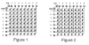
I'm planing on doing an 40x24 led display (modules of 8x8 led dot matrix).
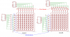
I was thinking on using 74HC595 in the coluns and a CD4017 in the rows.

Each column will always have only 1 led lit at one time, but one row can have all leds lit.
I have seen many projects where they are driving the leds directly from the 74HC595, but, here comes the first question:
-> Each channel should only provide max 35mA, more than enough for one led at 20/15mA. But if, on this CI, we have all leds 8 leds lit, we will be using, in total, 160mA @ 20mA/led.
The Icc/Ignd is only 70mA. Wouldnt this destroy the 74HC595? If so, please recommend me an power driver capable of sourcing at least 20mA at each channel, or another shift register with latch, as the 74HC595, but capable of sourcing these current.

Second question,
if we have an entire row lit, we will have 800mA @ 20mA/led. Is there any IC that can sink this current? Something like the ULN2803A. If possible, I would like the IC to be capable of sinking 1A just to be sure, but if you think that that isnt necessary, please tell me =)

Last question, depends on the second question solution,
Would it be better to use the IC from question 2 or simply some NPN transistors like the PN2222A? This would be a very cheap solution, because I can get these at around 4 Euro cent (0.04€) each.


Thanks a lot!
Freiheitpt
 
Question 1:

After a quick search, I didn't find an IC like the 74HC595 that could handle your current requirements. I believe the 70 mA limit for that IC is based mostly on it's capability (or lack thereof) to reject heat. If you allow more than 70 mA to flow through it, it will get very hot and eventually fry. You might be able to get around this if you add some sort of heat sink but I wouldn't recommend it.

Your best bet would be to add some transistors in between the outputs of the 74HC595 and each column. Since only 1 LED per column will be lit at a time, something like the BC547 or equivalent should work fine. Place a current limiting resistor for the LED between the emitter and the column and you won't need a base resistor. You can also use a transistor array if you can find one that meets you needs.

Question 2:

See question 3.

Question 3:

I would have the outputs of the 4017 drive transistors to sink each row's current however, the PN2222A only has a 500mA collector current. Here are some potential transistors to use instead of the PN2222A.
 
hi vne,
There is this power S/R, not cheap.:D

hi vne,
I could not reopen either.??
So deleted and reloaded.

Still not working, will advise EM..
 
Last edited:
Hey Eric. That pdf isn't opening up for me. It's just a blank screen. Not sure if it's only my problem but I can't view it.
 
These dual pfet's (irf7304) have been working for me as high side row drivers in a multiplexed 8x8 RGB led configuration. That would be 480ma max, but haven't been using all white much either.
 
vne147,
Thanks for your answer.

About the 70mA, that is what I have suspected too, but I do not understand why, maybe 80% of all projects I have seen, they drive the leds directly with the 74HC595, and on each port only having a weak resitor, something about 80-180 ohms.
But in this case, the 74HC595 was sinking the current and not powering.
But still, the Icc/Ignd is 70mA, so I suppose that the effect would be the same.

About the transistors, there are some cheap 500mA (90 Euro cent) transistor array to sink the current wich would be controled by the 74HC595.
Then, I would have only to get some transistors to power the rows.

I think, correct me if i'm wrong, this would be the easiest, cheapest way, and I would have less components on the board.

This is the solution I thought of, with everything I have read on forums/other projects/some datasheets, because sinking is easier than powering, and even a lot cheaper.
If can get my hands on some cheap 1A NPN transistors, I could drive an entire row of 40 leds, using each, 20mA. If I use 15mA, I could use a 800mA transistor, and the leds, I think, would be still bright enough. once again, please correct me if I'm wrong.
Another option, would be to use cheap 200mA transistor array to power the rows (or some transistors) and sink them with some cheap transistor array.
This second option, I think it would be more expensive than the first one, because I have to sink 800mA max. In the first option I would only have to sink 200mA.

Which would you recommend?

About the PN2222, i have seen a lot of different ones... some that are capable of 600mA, others of 800mA, and others of 1A. search for this transistor in the site tme.eu, and there they say that that transistor supports 1A. Because of these different numbers, I'm confused, and thats the reason I also asked here in the forum, hoping that you would also come across these numbers.

In the future, when I have a little bit more money, I would like to adapt this to RGB led dot displays, in wich I would have, 3x more components on the columns. But this is another story.

vne147,
thanks also for your reply, I will have a look on that.

Sorry for the big text =)

Freiheit
 
Here you have it.

Note:
Case 1 has sink elements at ?1 and power elements at ?2
Both cases 2 and 3 have sink elements at ?2 and power at ?1

I havent drawn the resistors in the "draft-schematic" just to keep it simple. Dont worry, I wont forget them ;)


btw, I suppose that the cheapest cenario would be the case 1. If you have a different opinion, please share it with me =)

Thanks a lot!
 

Attachments

  • Scannen0001.jpg
    Scannen0001.jpg
    235.4 KB · Views: 179
About the 70mA, that is what I have suspected too, but I do not understand why, maybe 80% of all projects I have seen, they drive the leds directly with the 74HC595, and on each port only having a weak resitor, something about 80-180 ohms.
But in this case, the 74HC595 was sinking the current and not powering.
But still, the Icc/Ignd is 70mA, so I suppose that the effect would be the same.

My interpretation of the data sheet is that it doesn’t matter whether the outputs are sourcing or sinking current. You are limited to 35 mA per output up to 70 mA total for the entire device. I can’t speak to other projects that may have used the device in excess of its maximum rated values. Like I said though, if more than 70 mA was allowed to flow through the device, what would probably happen is it would overheat and become damaged. Exactly how fast this happened would depend on the ambient temperature, heat rejection capability, and how much current there was.

About the transistors, there are some cheap 500mA (90 Euro cent) transistor array to sink the current wich would be controled by the 74HC595.
Then, I would have only to get some transistors to power the rows.

I think, correct me if i'm wrong, this would be the easiest, cheapest way, and I would have less components on the board.

Some people prefer to use transistor arrays over discreet components. In my opinion, there is not right or wrong approach in this case. It’s whatever you decide based on cost, availability, board size, etc.

This is the solution I thought of, with everything I have read on forums/other projects/some datasheets, because sinking is easier than powering, and even a lot cheaper.
If can get my hands on some cheap 1A NPN transistors, I could drive an entire row of 40 leds, using each, 20mA. If I use 15mA, I could use a 800mA transistor, and the leds, I think, would be still bright enough. once again, please correct me if I'm wrong.
Another option, would be to use cheap 200mA transistor array to power the rows (or some transistors) and sink them with some cheap transistor array.
This second option, I think it would be more expensive than the first one, because I have to sink 800mA max. In the first option I would only have to sink 200mA.

Which would you recommend?

I’m not really sure that I understand your statement about sinking being easier than powering. For this project, you will need to control the supply of current to the LEDs (sourcing) and you will need to control when and where that current is allowed to reach ground (sinking). Unless both of these aspects are properly addressed, your project probably won’t work the way you expect it to.

LEDs only allow current to flow in one direction. So, whether columns or rows source or sink is dependent on the specific type of matrix you purchase. Figure 1 shows a matrix where the anodes (+ side) of the LEDs are connected to the columns. In this case, the components providing the current (sourcing) would need to be connected to the columns and the components sinking the current would have to be connected to the rows. Figure 2 shows the opposite scenario. Which type of LED matrix are you using or planning to use?


Another option, would be to use cheap 200mA transistor array to power the rows (or some transistors) and sink them with some cheap transistor array.
This second option, I think it would be more expensive than the first one, because I have to sink 800mA max. In the first option I would only have to sink 200mA.

Which would you recommend?

In your case, you have 40 columns and 24 rows. Since you have stated that only 1 LED per column will be lit at any one time, the maximum current a column’s component will have to source or sink is the current from 1 LED or about 20 mA. For the rows, the maximum is 24 times that or about 480mA. You can have the rows source and the columns sink or vice versa. There is no wrong or right way. You should make this decision based on the specific LED matrix you choose. Know this though, however much current you allow into your circuit is exactly how much current will be leaving it. So, regardless of which direction you choose, the components controlling the columns will always have to source or sink 20 mA and the components controlling the rows will always have to source or sink 480 mA. The total current will not change and in general, the components don’t care whether they are connected to the anode of the LED (sourcing) or the cathode of the LED (sinking).

About the PN2222, i have seen a lot of different ones... some that are capable of 600mA, others of 800mA, and others of 1A. search for this transistor in the site tme.eu, and there they say that that transistor supports 1A. Because of these different numbers, I'm confused, and thats the reason I also asked here in the forum, hoping that you would also come across these numbers.

I googled PN2222A and looked in the first datasheet that came up. That’s where I got the 500 mA from. However, I went back and looked at a bunch of datasheets for the PN2222A from different manufacturers and the rated currents are indeed different. That’s interesting how the collector current is different for different manufacturers of the same part number. Maybe they have different ways of testing and that’s why the numbers are different? I really have no idea. Check out the link. My favorite one is from National Semiconductor where they say on the same page that the device is for switching collector currents up to 500 mA and then in the table below it says maximum continuous collector current is 1A. Maybe the larger packages are the higher current ones but it wasn’t obvious to me.

PN2222A Datasheets
 

Attachments

  • 8x8 LED MAtrix.PNG
    8x8 LED MAtrix.PNG
    27.8 KB · Views: 150
About beeing easier to sink than to drive, and a lot cheaper, is just what I found googling around.
Taking this in consideration, and as we have more columns than rows, the cheapest way would be sinking on top (columns), and sourcing at the side (rows).

I prefer IC's too, but power IC's, for sourcing this, are way too expensive. With discrete elements, I could do this, for each 8 rows, for less than 1Euro, and with IC it would be for +/- 3Euro.
And obviously that board size matters too, and since we would need a lot more discrete components on the columns, a way to have have a little of the 2 worlds (board size and low cost), would be sinking on the columns with IC (wich are also very cheap - 0.90 Euro each 8 channel IC) and sourcing at the rows with the PN2222A or similars, wich, are also very cheap. And as we have less rows than columns, we have also only a "few" discrete components.

My LED matrix is a common anode, So I have to source the, normaly, the rows, and actualy, it is also what would be the cheapest. But with common anodes matrix, I could also source at the columns, because it is just a matter of wiring. I have read that common anodes/cathodes, in the Led Matrixes, are, in fact, only to tell us if the rows are of the matrix are anodes or cathodes.

About the rows, I think your are mistaken. In each row, we have 40 columns, and these 40 leds need to be sunk. it would be arround 800mA.

I agree that the numbers with the PN2222A are very confusing.

I dont want to be doing this project and at the end having a little bomb xD
 
Last edited:
About beeing easier to sink than to drive, and a lot cheaper, is just what I found googling around.
Taking this in consideration, and as we have more columns than rows, the cheapest way would be sinking on top (columns), and sourcing at the side (rows).

I prefer IC's too, but power IC's, for sourcing this, are way too expensive. With discrete elements, I could do this, for each 8 rows, for less than 1Euro, and with IC it would be for +/- 3Euro.

I still don't understand why it's easier to sink than to drive but you seem convinced of it so I'll move on. Attached to this post is a diagram I created showing two arrangements.

Circuit A shows an arrangement using an 8x8 matrix where the LED's anodes are connected to the columns and the cathodes are connected to the rows. In this arrangement the transistors connected to the columns are sourcing or driving the current and the transistors connected to the rows are sinking the current. Each column's transistors must tolerate 20 mA and each row's transistor must tolerate 800 mA.

Circuit B is the opposite of A and shows an arrangement using an 8x8 matrix where the LED's cathodes are connected to the columns. In this arrangement the transistors connected to the columns are sinking the current and the transistors connected to the rows are driving or sourcing current. Each column's transistors must tolerate 20 mA and each row's transistor must tolerate 800 mA.

Do you see that it doesn't matter whether it's the columns or the rows that are sourcing the current because you'll still need the same number of components capable of tolerating the same current flow for both arrangements. Which ever power transistor array you're looking at that's too expensive to use in the rows is the same array you'd need regardless of what's sourcing or driving and what's sinking. So, I'm not seeing how one option saves money over the other.

Maybe there are some nuances to your project you haven't yet shared which could clarify your view point?


My LED matrix is a common anode, So I have to source the, normaly, the rows, and actualy, it is also what would be the cheapest. But with common anodes matrix, I could also source at the columns, because it is just a matter of wiring. I have read that common anodes/cathodes, in the Led Matrixes, are, in fact, only to tell us if the rows are of the matrix are anodes or cathodes.

It is not simply a matter of wiring. The arrangement you choose must be consistent with the type of display you are driving. Back to my diagram, in circuit A the columns are driving and the rows are sinking. In circuit B, it's the opposite. I chose to drive the columns in circuit A and sink the rows because if I did the opposite, the display would not work. LEDs only allow current flow in one direction. If you took the display in circuit A, connected V+ to the row, and ground to the column it would not work.


About the rows, I think your are mistaken. In each row, we have 40 columns, and these 40 leds need to be sunk. it would be arround 800mA.

You're right, I made a mistake. It should have be 20mA multiplied by 40 not 24.


Is this making sense at all? If not, maybe someone else can chime in and take a whack at explaining it to you or show me where my thought process has gone wrong.
 

Attachments

  • 8x8 comparison.PNG
    8x8 comparison.PNG
    117.6 KB · Views: 168
About the sinking and sourcing elements, i didnt meant that it was easier for us, but its easier to the manufacturer of IC's to make sinking IC's than sourcing IC's. I don't know why either, its just what I have read.

I know that leds only allow current to flow in one direction, they are like diodes.
About the wiring thing:
Lets assume we have only 1 matrix common cathode.
you arrange them in 3x10 (total leds: 24x80). And then you would source the columns and sink the rows. But lets rotate this display 90 degrees. Now you have 80x24, and for "our eye" we are sourcing the rows. But obviously, the matrix rows/columns switched places.
I hope that this will help to clarify what I wanted to say.

About beeing cheaper/expensier.
My displays are common anode.
So I will be sourcing the rows and sinking the columns.
We have 24 rows. If I use discrete transistors, I would only pay in total 1.75 USD.
If I use transistor arrays to power the rows, I wouldnt pay less than 12.88 USD.

Then, in the columns, If I use discrete transistors I would pay in total 2.9USD
But if i use transistor arrays, I would pay in total 3.94USD.

To eliminate the biggest cost, I would use in the rows discrete transistors and the whole project would be cheaper.

Thanks


P.S.: Wich is the software you use for drawing those squematics?
 
Last edited:
The point about you switching back and forth what you call rows and what you call columns is an important one if you want someone to understand your though process.

The software I used to create the schematic is called Eagle. There is a free version that supports board sizes up to about 3"x4". Here's a link:
 
Sorry vne147. But my english is not perfect. Its easy to explain everything correctly in Portuguese, but technical english is not that easy, although, normal/daily english its somehow easy for me. Just that I havent written or spoken english for some time now. sorry again.
But you have already answered all my questions, directly or indirectly.

Thanks a lot for your help and sorry for all the confusion and the whole work.
 
Status
Not open for further replies.

Latest threads

Back
Top