DirtyLude
Well-Known Member
This should be a fairly simple question.
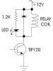
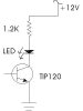
I have a microcontroller activating a TIP120 that will drive a relay. I would like a status LED that tells me that the microcontroller is turning the TIP120 on. I figured I could kill 2 birds with one stone here and use an LED to show me the status and to limit current to the base of the TIP120.
I've tried it out and it works. I simply replaced the 10k current limiting resistor with an LED. Using a multimeter it shows the specific LED's I would be using have 8k resistance, which should be fine. Since the TIP120 is pulling current it also prevents the LED from getting too much current in turn.
I just wanted to make sure there's nothing technicaly wrong with doing this. Also, if the LED blows for any reason, will it stop the circuit all together, or will current still pass though?