Continue to Site

Welcome to our site!

Electro Tech is an online community (with over 170,000 members) who enjoy talking about and building electronic circuits, projects and gadgets. To participate you need to register. Registration is free. Click here to register now.

  • Welcome to our site! Electro Tech is an online community (with over 170,000 members) who enjoy talking about and building electronic circuits, projects and gadgets. To participate you need to register. Registration is free. Click here to register now.

Learning Atmel ARM micros

Status
Not open for further replies.

SimonB

New Member
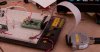
I am trying to learn the ARM7 core using an Atmel SAM7S development board. All I want to do is flash an LED on and off - a 2 minute job with a PIC.

Does anyone else share my opinion that the Atmel example code is way way overcomplicated?

Looking at their example projects that flash LEDs, they define functions that call other functions that are defined in another file. Look into this other file and the function you are looking for calls another function, using variable that are defined in yet another file.... and so it goes on.

Does anyone with experience of ARMs (and Atmel) agree?

ST, TI and Luminary sample code seems to be a whole lot easier...

Please let me know

Thanks

Simon
 
Are you just playing with the ARM chip or have an end application in mind? I only ask becasue as you have found the ARM is not as easy to write code for as other Uc. Why do you need that much processig power?

What language are you using?
 
I worked quite a bit with the SAM7 and SAM9 - i didn't find it over complicated. The AT91Lib wraps all of the registers with C functions which i found were usually poorly designed and pretty ugly to use - perhaps this is the source of your confusion. Some of the demos were poorly written as well, but i always consulted the datasheet first to understand how to operate a peripheral. I suggest you do the same - first understand how to operate the peripheral directly and only then decide if you want to use the AT91Lib's implementation.
 
Hi Andy / Pavius

Thanks for your comments. I am writing in C. I am brave, but not daft enough to attack the ARM in assembler:eek: I have had 15 years of writing code for the PIC (in assembler and C) and thought I would stretch my wings a little

I am looking at their "getting started" project. Here goes...:

They use the following line, just to define a pin:

/// LED #0 pin definition (PA0).
#define PIN_LED_DS1 {1 << 0, AT91C_BASE_PIOA, AT91C_ID_PIOA, PIO_OUTPUT_1, PIO_DEFAULT}

Firstly I do not understand what this line is doing. I understand the 1<<0 from C, but what's with all the jargon after it? Are we calling a function here...?

The only time this definition is use is 3 lines later in:

#define PINS_LEDS PIN_LED_DS1, PIN_LED_DS2, PIN_LED_DS3, PIN_LED_DS4

There must be an easier way....

They also call the CP15 (coprocessor 15) which is hardly needed to drive an LED from an interrupt. why?

It just seems that they are using way too much code when it is not really needed.... or is it...?

Can you shed any light on this...? the other manufacturers do not seem to do this.

I have no problem with the AT91SAM7S...h file and agree with you that it tidies up a whole ton of configs.

I guess it is just more aggro to wade through when I am trying to learn the J-Link and the architecture and get my head round pointers to structures etc... all of which is alien to me and the world of the PIC!

Any further advise would be greatly received!

Thanks

Simon
 
It has been many months since i last touched the sam7 so while that does look familiar, i don't recall the specifics. I suggested you look at the registers required to drive the peripherals (GPIOs included) - not program in assembler. Knowing which registers need to be set will help greatly in understanding what you need to do.

Anyway, there is an active at91 board @ https://www.at91.com/. I'm sure they will explain everything you need to know off the top of their head.
 
Last edited:
What sample code are you using?

Here's a program I played with a long time ago to play with GPIO and edge interrupts. I'm assuming it still works. Haven't looked at it in a long time. It's pretty well documented inline. If you want me to trim out the input and interrupt stuff to make it simpler, I can.

Because ARM's tend to be more powerful uC's, they allow programming to be a little more obscure, so you see people writing for ARM's the way they would write for something like Linux.

Like mentioned, just go through the datasheet and learn the registers. Unfortunately they can be quite complex sometimes, since they try to handle everything.

[EDIT: Got rid of the edge interrupt code]
Code:
#include <AT91SAM7S256.h>

#define nop()  __asm__ __volatile__("nop")

#define LED            (1<<0)   // PA0
#define INPUT_PIN      (1<<1)   // PA1
#define INT_PIN        (1<<2)   // PA2

static void initialize( void);
void delay_us( int time);
void delay_ms( int time);

int main(void)
{
  int delay = 100;
  volatile long input;
  initialize();
  enableIRQ();
   
  volatile AT91PS_PIO pPIOA = AT91C_BASE_PIOA;

  while(1)
  {
    input = pPIOA->PIO_PDSR;          //for debugging.  Watch input variable to check if inputs working.
    
    if(( pPIOA->PIO_PDSR & INPUT_PIN) == INPUT_PIN)
      delay = 1000;
    else
      delay = 100;
        
    pPIOA->PIO_CODR = LED;
    delay_ms(delay);
    pPIOA->PIO_SODR = LED;
    delay_ms(delay);

  }
} 

static void initialize(void)
{
  //Turn on the peripheral clock.  Without this on, inputs do not actually register in the PDSR register   
  volatile AT91PS_PMC	pPMC = AT91C_BASE_PMC;			// pointer to PMC data structure
  pPMC->PMC_PCER = (1<<AT91C_ID_PIOA);				// enable Timer0 peripheral clock

  volatile AT91PS_PIO pPIOA = AT91C_BASE_PIOA;
  pPIOA->PIO_PER = (LED | INPUT_PIN);         // Set PIO to control LED and button.    
  // Initialize Input
  pPIOA->PIO_ODR = INPUT_PIN ;                // Disable outputs for INPUT pins. (not needed as all pins default input on reset)
  pPIOA->PIO_PPUER = INPUT_PIN;               //Pullup Enable (not needed as all pullups are enabled on reset)

  // Initialize Output
  pPIOA->PIO_OER = LED;                      // Enable output for LED.
  pPIOA->PIO_SODR = LED;                     // Turn LED off.
  pPIOA->PIO_PPUDR = LED;                    //Pullup disable
}

void delay_us(int delay)
{
  while(delay--)
  {
      __asm volatile (" NOP");
      __asm volatile (" NOP");
      __asm volatile (" NOP");
      __asm volatile (" NOP");
      __asm volatile (" NOP");
      __asm volatile (" NOP");
      __asm volatile (" NOP");
      __asm volatile (" NOP");
      __asm volatile (" NOP");
      __asm volatile (" NOP");
      __asm volatile (" NOP");
      __asm volatile (" NOP");
      __asm volatile (" NOP");
  }
}

void delay_ms(int delay)
{
  char i;
  while(delay--)
  {
    for(i=0; i<4; i++)
    {
      delay_us(250);
    }
  }
}
 
Last edited:
Hi Mark

This is an excellent post... although I do not understand the 1U bit. Thanks. It seems to do (simply) what Atmel want to do in a way too complicated way. I will plug it into my IAR compiler and see how I get on.

Incidentally, do you understand the following line?

#define PIN_LED_DS1 {1 << 0, AT91C_BASE_PIOA, AT91C_ID_PIOA, PIO_OUTPUT_1, PIO_DEFAULT}

Also, another thing that has been buggin' me. Why does the ARM have an enable register AND a disable register for all the config registers?

Please let me know and I will let you know how I get on...

Thanks once again

SImon
 
Hi Mark

This is an excellent post... although I do not understand the 1U bit. Thanks. It seems to do (simply) what Atmel want to do in a way too complicated way. I will plug it into my IAR compiler and see how I get on.

The U is just an octal indicator, like h would be for hex. I usually don't use that and it's a left over from a previous cut and paste. The define would work just as well like:

#define LED (1<<0) // PA0

Since the registers are 32bit, it's much easier to define bit definitions in terms of how many positions they are shifted to the right rather than trying to type out 32 0's and 1's. PA0 is the right most bit, so it's 0x00000001 shifted over 0 times to the left.

Incidentally, do you understand the following line?

#define PIN_LED_DS1 {1 << 0, AT91C_BASE_PIOA, AT91C_ID_PIOA, PIO_OUTPUT_1, PIO_DEFAULT}

It's a definition of an array of values. This is something like I was talking about. In order to make it easier for the person writing the code, they have grouped together a bunch of things specific to the GPIO in one place, including the base address, and the device ID. It should make it easier to change things if they need to be changed in the future, but makes everything a little more difficult to understand if your not used to the style.

Also, another thing that has been buggin' me. Why does the ARM have an enable register AND a disable register for all the config registers?
Because all the registers are 32bit, they have registers that all they do is one way toggle (set or clear) other registers. They also have registers that you can directly write to like you would a PIC, and they have mask registers so that you can mask off specific areas of the registers so you don't effect everything with your writes.

It means there's really one register and a bunch of registers that manipulate it in different ways.

For example, the PIO_ODSR is the output register, just like in a PIC. If you write to it, the pins change (if they are set to output). Most people don't use this directly though, unless they need to twiddle a bunch of bits directly. They use the registers that effect this one.

PIO_SODR sets any output to 1 that you send to it. So, if you want to turn pin one on, you would write 0x00000001 to
PIO_SODR. This helps, because no other output is effect by this write. PIO_CODR does the opposite, and writing 0x00000001 to PIO_CODR turns pin 1 off without effecting anything else.

If you want to write to the PIO_ODSR directly, there is a mask to make sure you don't effect pins you don't want to effect. PIO_OWSR (output write status), and it has it's own associated set and clear registers, PIO_OWER (enable) and PIO_OWDR (disable).

You can see it helps, but it also complicates things, since there are a lot of registers that essentially do nothing but effect the main working registers.

EDIT: cleaned up that code a bit. Removed the U's. Noticed there was a function definition that didn't exist anymore and a variable definition. syntax error, forgot to move one of the PIO->'s to PIOA->.
EDIT Again: Oh ya, and this code is specifically for the GCC/Crossworks. If you are using IAR, you'll need to modify some things. EnableIRQ() isn't actually needed in the code anymore, since I removed the edge interrupt functionality, so you can just remove it.
 
Last edited:
Hi Mark

Thanks for this. It is very detailed reply and answers a lot of outstanding questions. Yours is the first bit of code I understand in its entirity. I think the mists are clearing!

Simon
 
You get used to the registers. I've been playing with luminary micro Cortex-M3's and even though they are 32bit, it uses 8bit ports for some reason. So a port register is 24 unused bits, plus 8 that actually effect the specific port. I'm finding it painful. It also limits you to working with 8pin blocks which can be a pain as well.
 
Hi Mark

I give up. I'm going back to the PICs. I have loaded your code in. it all compiles OK, but when I step through it, once the registers have been configured, nothing changes. As the program loops, I cannot see any registers changing. How do I tell if my port pins are changing? The ODSR, SODR and CODR aren't doing anything.

OK, so try downloading it to my AS91SAM7S-EK.... then I get a whole load of breakpoint errors and messages about the JTAG interface and stack overflows...

Any thoughts would be appreciated, but I am beginning to wonder if all this is really worth it

Yours (with no hair left to tear out)

Simon
 
I don't use IAR, so I can't answer any debugging questions with it. In Crossworks, you can view memory and registers in a watch window.

Again, I don't use IAR, so I'm no help with the breakpoint/JTAG issues you are getting with it, either.

I'll compile and load the program again tonight to make sure I haven't made any silly errors, but it should work as is.
 
I've just downloaded Crossworks compiler. I will see how I get on with this!

Slowly sticking my hair back in again..:confused: (smiley with tufts of hair)
 
It's working fine for me. Here's the final code, but I think it's the same as the code above:

Code:
#include "AT91SAM7S256.h"

#define nop()  __asm__ __volatile__("nop")

#define LED            (1<<0)   // PA0
#define INPUT_PIN      (1<<1)   // PA1
#define INT_PIN        (1<<2)   // PA2

static void initialize( void);
void delay_us( int time);
void delay_ms( int time);

int main(void)
{
  int delay = 100;
  volatile long input;
  initialize();
   
  volatile AT91PS_PIO pPIOA = AT91C_BASE_PIOA;

  while(1)
  {
    input = pPIOA->PIO_PDSR;          //for debugging.  Watch input variable to check if inputs working.
    
    if(( pPIOA->PIO_PDSR & INPUT_PIN) == INPUT_PIN)
      delay = 1000;
    else
      delay = 100;
        
    pPIOA->PIO_CODR = LED;
    delay_ms(delay);
    pPIOA->PIO_SODR = LED;
    delay_ms(delay);

  }
} 

static void initialize(void)
{
  //Turn on the peripheral clock.  Without this on, inputs do not actually register in the PDSR register   
  volatile AT91PS_PMC	pPMC = AT91C_BASE_PMC;			// pointer to PMC data structure
  pPMC->PMC_PCER = (1<<AT91C_ID_PIOA);				// enable Timer0 peripheral clock

  volatile AT91PS_PIO pPIOA = AT91C_BASE_PIOA;
  pPIOA->PIO_PER = (LED | INPUT_PIN);         // Set PIO to control LED and button.    
  // Initialize Input
  pPIOA->PIO_ODR = INPUT_PIN ;                // Disable outputs for INPUT pins. (not needed as all pins default input on reset)
  pPIOA->PIO_PPUER = INPUT_PIN;               //Pullup Enable (not needed as all pullups are enabled on reset)

  // Initialize Output
  pPIOA->PIO_OER = LED;                      // Enable output for LED.
  pPIOA->PIO_SODR = LED;                     // Turn LED off.
  pPIOA->PIO_PPUDR = LED;                    //Pullup disable
}

void delay_us(int delay)
{
  while(delay--)
  {
      __asm volatile (" NOP");
      __asm volatile (" NOP");
      __asm volatile (" NOP");
      __asm volatile (" NOP");
      __asm volatile (" NOP");
      __asm volatile (" NOP");
      __asm volatile (" NOP");
      __asm volatile (" NOP");
      __asm volatile (" NOP");
      __asm volatile (" NOP");
      __asm volatile (" NOP");
      __asm volatile (" NOP");
      __asm volatile (" NOP");
  }
}

void delay_ms(int delay)
{
  char i;
  while(delay--)
  {
    for(i=0; i<4; i++)
    {
      delay_us(250);
    }
  }
}
 

Attachments

  • 20090922-basic_led_sam7-001.jpg
    20090922-basic_led_sam7-001.jpg
    233.9 KB · Views: 834
  • basic_led.png
    basic_led.png
    160.8 KB · Views: 671
Hi Mark

I really appreciate this. I have just downloaded the crossworks compiler and got the license code. All will go quiet over the next couple of days while I get my head around this.

I posted a note on the AT91.com forum and I got the answer back suggesting I start with one of the worked examples, which I am convinced import far too many files to simply flash an LED.

I will have a go with Rowley and see what this throws up...

Thanks once again and you did not have to photograph the LED working - I believed you! The screenshot of your register settings was most helpful though!

Simon
 
could any one goive me free Asemler for ARM based MCUs

The only free assembler/compiler I know of is GNUARM. You can take a look at YAGARTO, which is a GNUARM toolchain. I played with it for a while and and got totally frustrated.

Thanks once again and you did not have to photograph the LED working - I believed you! The screenshot of your register settings was most helpful though!

I like showing off my MAD TITE LED skillz.
 
Any reason you didn't go to the 32bit PICs (MIPs core) as you're already familiar with PICs and probably have the tools you need already?
 
I do indeed have experience with both...the Atmel code is worse than useless! Buggy and convoluted as hell!

That said, I was working with that crap 8 years ago. They may have improved it a bit, but I doubt it since most of the garbage was to try and common out all their variations.

Dan
 
Hi Ubergeek.

Strong words in deed, but I must say I think convoluted is the word for it. Sometimes writing code in a convoluted way makes it easier to edit if part of a larger system, but when trying to learn the architecture it makes it a nightmare. I think Atmel could have made their 'Getting Started' code a lot simpler. I will persist though...
 
Status
Not open for further replies.

Latest threads

New Articles From Microcontroller Tips

Back
Top