Continue to Site

Welcome to our site!

Electro Tech is an online community (with over 170,000 members) who enjoy talking about and building electronic circuits, projects and gadgets. To participate you need to register. Registration is free. Click here to register now.

  • Welcome to our site! Electro Tech is an online community (with over 170,000 members) who enjoy talking about and building electronic circuits, projects and gadgets. To participate you need to register. Registration is free. Click here to register now.

LCD

Status
Not open for further replies.

2PAC Mafia

Member
Hi guys,

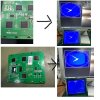
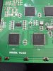
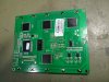
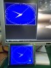
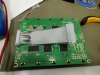
we have been working with a LCD adaptation to an electronic unit which has obsolete original component. We bought 2 units and made them working properly. When we wanted to make more of them we received a different type of unit of LCD and now the new ones are not working. In theory they are fully compatible. Do you have any idea?

The LCD´s are 160x128 8080 parallel port based on chip T6963.
 

Attachments

  • Conexiones segundo LCD.jpg
    Conexiones segundo LCD.jpg
    82.2 KB · Views: 101
  • Explanation of problem.jpg
    Explanation of problem.jpg
    176.5 KB · Views: 102
  • Model of good LCD.jpg
    Model of good LCD.jpg
    166.5 KB · Views: 96
  • Model of not working unit.jpg
    Model of not working unit.jpg
    180 KB · Views: 95
  • Test of working unit.jpg
    Test of working unit.jpg
    121.8 KB · Views: 104
  • Working unit LCD.jpg
    Working unit LCD.jpg
    121.9 KB · Views: 99
On the good ones the chip is RA6963 and on the not working ones we have the SAP1024B
 
LCDs in general are tricky to work with, because they are timing sensitive.

Especially the SPI (serial) ones.

More than likely the new display has a different timing need, and needs to be adjusted for in software.

Carefully check the timing specs of both displays and compare them side by side.
 
it's difficult to tell from the pictures exactly what is causing your problem. one thing i can tell you is that the smearing effect on the non-working panel is not normal, even for a panel getting confused signals. it looks like the new panel is supposed to be a replacement for the old one, judging by the part number on the sticker. but even then, without more documentation than the connector pinout (a schematic would be ideal, but a data sheet with the signal, power, and data timing information (for both boards) would be a big help. the smearing problem appears to be something more wrong than just incompatibility of the interface, so it could be you have a defective panel.
 
I use a lot of different Toshiba modules.. I have used all three of those chipsets..

From what I see the -15v isn't strong enough I used a separate -15 v convertor ( Now almost extinct!!) the MAX xxx ( can't remember the exact model ) Give a good strong negative voltage.... Some of these units make their own... What size resistor do you have on the -ve to Vo?


Actually... The "Good one" Has the -Ve on board.... The non working doesn't seem to have one..
 
Thank you guys. Finally we received a datasheet from China and we saw the non working displays needed negative voltage on Vcc (pin 4). It is needed to install a potentiometer between pin 4, 5 and GND.

On the good one, first on, on pin Vcc (pin 4) uses +5V. We have tested it and that was the difference!!!
 
Status
Not open for further replies.

Latest threads

New Articles From Microcontroller Tips

Back
Top