Continue to Site

Welcome to our site!

Electro Tech is an online community (with over 170,000 members) who enjoy talking about and building electronic circuits, projects and gadgets. To participate you need to register. Registration is free. Click here to register now.

  • Welcome to our site! Electro Tech is an online community (with over 170,000 members) who enjoy talking about and building electronic circuits, projects and gadgets. To participate you need to register. Registration is free. Click here to register now.

Help! My LCD isn't working

Status
Not open for further replies.

18muneys

New Member
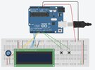
Whilst my circuit works online perfectly, the LCD won't even turn on irl.
The bullet points below cover basic problems that haven't solved my problem

- I've meticulously checked my wire connections, so that they're the exact same as online and securely connected, and bought the LCD already soldered (I think they're soldered perfectly fine).
- The Arduino is turning on, but no response from my LCD (except from when I removed the wire connected to the E pin and got small flashes on the side, or whilst I was checking the VSS and VDD pins I saw light flashes - so I THINK its a working LCD)
- The code works online, so I copy/pasted onto the Arduino app, downloaded 'LiquidCrystal' library for the '#include <LiquidCrystal . h>' bit. ( idk if it matters but I did it anyways)

My voltmeter is labelled 'B10k' so I'm assuming that means 10k ohms, like my online circuit, so I don't think its my voltmeter but idk, that could be it because...
I assume the problem is something to do with the backlights (I've toggled around the potentiometer and literally nothing happened) ?? Either that or connection issue, but idk how due to the first bullet point.
Soooo I'm stuck, I have no clue what the problem is, although this is my first proper use of Arduino so I'm assuming it's a simple issue I'm overlooking?
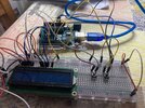
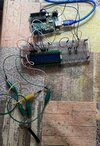
I've added pictures of my circuit (sorry for the messy wires - hopefully it should be easy to see it's the same as online) and a copy of the code, because at this point the problem could be anything.....
 

Attachments

  • Screenshot 2023-03-11 at 20.22.38.jpeg
    Screenshot 2023-03-11 at 20.22.38.jpeg
    313.1 KB · Views: 207
  • copy_of_arduino_stopwatch1.ino
    864 bytes · Views: 221
  • IMG_2483.jpeg
    IMG_2483.jpeg
    3.5 MB · Views: 213
  • IMG_2482.jpeg
    IMG_2482.jpeg
    4.2 MB · Views: 227
  • IMG_2481.jpeg
    IMG_2481.jpeg
    3.5 MB · Views: 221
Something to consider with your solderless breadboard is the power rails. Are they continuous on each side? I see your jumper side to side but does each rail extend the full side of the board? Just as an example:

Breadboard.png


Note how the red and blue power rails extend the full length of the board. Some boards have breaks in between the sections.

Next for future plan you may want to consider one of these which make for simple because they come assembled including the I2C interface ready for use. Vcc and GND plus SCL and SDA only 4 lines to your uC.

Assuming yours has power and your code includes the LCD Backlight it should at least light. The last two pins A and K, or anode and cathode are for the LED back light. You may want to give this a read and try their code sample just to see if your display shows forms of life. Again make sure the LCD is getting power.

Ron
 
In your sketch, You need to associate the pins used with their operation .. .. .

For example ..

C:
#include <LiquidCrystal.h>

//const int rs = ?, en = ?, d4 = ?, d5 = ?, d6 = ?, d7 = ?; // <<<<<<<<<<< associate pins

LiquidCrystal lcd(7, 6, 5, 4, 3, 2);

void setup()

Many simulators assume this internally, but the Uno needs telling.

MM
 
I agree with Reloadron, you have used two breadboards which are shorter than the one in your "schematic layout" diagram,
Looking at the pictures of your build, you do not seem to have any links between the power rails on the two breadboards.

JimB
 
Add a cap across the supply rail too. Check all grounds and Vdd.
 
Something to consider with your solderless breadboard is the power rails. Are they continuous on each side? I see your jumper side to side but does each rail extend the full side of the board? Just as an example:

View attachment 140794

Note how the red and blue power rails extend the full length of the board. Some boards have breaks in between the sections.

Next for future plan you may want to consider one of these which make for simple because they come assembled including the I2C interface ready for use. Vcc and GND plus SCL and SDA only 4 lines to your uC.

Assuming yours has power and your code includes the LCD Backlight it should at least light. The last two pins A and K, or anode and cathode are for the LED back light. You may want to give this a read and try their code sample just to see if your display shows forms of life. Again make sure the LCD is getting power.

Ron
This was one of the two problems before my circuit started working (which it does now, so thank you so much!). Once I connected the breadboards with wires, the backlight started working, but the potentiometer was off. So I directly connected each of the potentiometers pins the the power rail and designated pin for the LCD on the breadboard, and it worked (after adjusting the contrast of course)!
 
Glad it came together and worked out for you. :)

Ron
 
This was one of the two problems before my circuit started working (which it does now, so thank you so much!). Once I connected the breadboards with wires, the backlight started working, but the potentiometer was off. So I directly connected each of the potentiometers pins the the power rail and designated pin for the LCD on the breadboard, and it worked (after adjusting the contrast of course)!
Good to know that your project is working finally. By the way, if you consider making a PCB, you can use an Arduino Nano instead of UNO. You can make a PCB like this:


That will make your project compact.
 
Status
Not open for further replies.

New Articles From Microcontroller Tips

Back
Top