Continue to Site

Welcome to our site!

Electro Tech is an online community (with over 170,000 members) who enjoy talking about and building electronic circuits, projects and gadgets. To participate you need to register. Registration is free. Click here to register now.

  • Welcome to our site! Electro Tech is an online community (with over 170,000 members) who enjoy talking about and building electronic circuits, projects and gadgets. To participate you need to register. Registration is free. Click here to register now.

LCD Power Supply

Status
Not open for further replies.
Im just using the generics term The electrolytics and the inductors or chokes are a filter network to take the AC component or any DC variations out of the B+ or supply voltage. At lower power supply frequencies the filter caps have to be larger typically 450uF - 2000uF and are a direct short for AC to ground.Chokes are not that common anymore but were placed in series with the load and presented a high impedance to AC. A typical PI ckrt was Cap to gnd then a choke then another cap to gnd. Since heat dries out electrolytics it is beyond me why they miunt them next to the heat sinks unless they have it down to a science whereby they dry out as soon as the warranty is over.

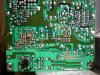
In yourphoto the 2 caps lower right are in the 24 volts supply and should be replaced with 35 volt caps. They produce the symptom of shutdown after a few seconds.
Smaller caps in the picofarad range are used to filter RF or higher freqs.
 
Last edited:
The five I replaced already (in the lower left, in the larger of the two photos) were 100uF, 220uF, and three 1000uF. All 35v to begin with, so I replaced them all with 35v.

The two on the right are also presently 35v, 2,200 uF. Haven't replaced those yet.

Okay, back to study your (wonderful) schematic, and study what I've got here in my hands...
 
Last edited:
Hi KeithU,

I have the same PSB as you have, and the same problem. where you able to find the schematic for your board, or did you fix your board?
any input will be greatly appreciated.
 
THANKS for the respond, and sorry to have bothered you, good luck with the other projects.

Any input from the other members like Karyoker or chriss123 would be greatly appreciated.
 
That is not the power supply I have but if you have a macro camera, a photo of a partial trace such as this would help. Notice I am using direct sunlight.. The jpg is imported into paint and traced.
 

Attachments

  • bot.jpg
    bot.jpg
    237.9 KB · Views: 672
Last edited:
No bother at all, in fact, while I'm sorry for you, I'm glad that we share a common problem, and am optimistic that we'll narrow down the defective part(s).

:)

Keith
 
THANKS karyoker for the quick respond, I am an armature 62 years old with electronics, but very good at soldering and paint program, I hope this pics represent your board.

Sorry for the delay, I am still having a problem posting the image from my desktop. I will keep trying don't give up on me please.
 
Can someone please ex plane how to insert an image attachment into this. THANKS

**broken link removed**
 
Last edited by a moderator:
resize the image to 1200 and save. Click manage attachments. Browse to the folder where you saved select the image then click upload.
 
I am very sorry, excuse my ignorance, I can build computers but I am not good with these things, where is manage attachments? and is that 1200 KB ?
 
Download irfanview. It allows you to resize photos Resize to 1200 X and preserve ratio then saveas. Manage attachments are below in additional optionswhen you are posting. (scroll down)
 
Download irfanview. It allows you to resize photos Resize to 1200 X and preserve ratio then saveas. Manage attachments are below in additional optionswhen you are posting. (scroll down)

Followed instructions , after clicking upload, the bottom of page said done, but I see no Attachment after submitting reply
 
Last edited:
Initial observations Check components above discolored areas Resolder circled joints
 

Attachments

  • str.jpg
    str.jpg
    373.7 KB · Views: 551
Status
Not open for further replies.

Latest threads

New Articles From Microcontroller Tips

Back
Top