Continue to Site

Welcome to our site!

Electro Tech is an online community (with over 170,000 members) who enjoy talking about and building electronic circuits, projects and gadgets. To participate you need to register. Registration is free. Click here to register now.

  • Welcome to our site! Electro Tech is an online community (with over 170,000 members) who enjoy talking about and building electronic circuits, projects and gadgets. To participate you need to register. Registration is free. Click here to register now.

TDK Lambda power supply problems

Shagreobe

New Member
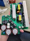
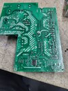
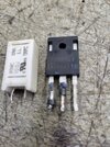
Hello electronics gurus. I have approx 20 power supplies(rectifiers) that the power boards are frying and won't start up see pics. They are blowing 4-10ohm resistors, a diode, The IC (L4981AD),and between 1&4 Mosfets. I cant find where or why they are doing it. HELP!!!
The fets go on the large heatsink, the resistors are near the relay by the big caps, diode is basically in the center of the board
 

Attachments

  • board top.jpg
    board top.jpg
    1.3 MB · Views: 116
  • board bottom.jpg
    board bottom.jpg
    1.7 MB · Views: 114
  • resister and mosfet.jpg
    resister and mosfet.jpg
    1.5 MB · Views: 98
  • data plack.jpg
    data plack.jpg
    58.4 KB · Views: 93
What voltage - current - frequency input and output are they?
I can only see three power terminals from the photos..

Are they generator controllers of some sort?
 
They are dc power supplies/rectifiers. Used for electroplating. Input voltage is 220VAC/1Ph/60Hz. It comes into another board with a few caps and inductors and splits to this board. One side goes to the single screw terminal on the far side. the other line splits into 2 wires and goes to power switch, then to the 2 spade terminals.
I was going to draw on the pic, but This is a new laptop and I havent installed all my stuff yet. I'll snap a pic of the whole unit on monday (off tomorrow yippee!)
 
the other line splits into 2 wires and goes to power switch, then to the 2 spade terminals.

OK, I did not notice the spade terminals to start with.

It appears they both go to bridge rectifiers; the one near the relay looks to be for the main output stage power, and the one along the edge possibly for control circuit power??

Please post more photos from different angles, so all the components are identifiable - and some of the other board??

The other board may have a "soft start" resistor on it to pre-charge the main capacitors before the relay pulls in and connects direct power. If so, that resistor is a possible culprit.
If the input power is cycled too frequently, those can easily be cooked in some PSU designs.
 

Latest threads

New Articles From Microcontroller Tips

Back
Top