Continue to Site

Welcome to our site!

Electro Tech is an online community (with over 170,000 members) who enjoy talking about and building electronic circuits, projects and gadgets. To participate you need to register. Registration is free. Click here to register now.

  • Welcome to our site! Electro Tech is an online community (with over 170,000 members) who enjoy talking about and building electronic circuits, projects and gadgets. To participate you need to register. Registration is free. Click here to register now.

Latched Circuit required for heavy load 400V to 600V.

Status
Not open for further replies.

Xen.Cloete

New Member
Dear fellow members,

I have been searching for some time now and have not found what I am looking for... and I am totally rusted in electronics. So let me get to it.

The project: (Woodworking Assisted Gadgets)
Circuit to receive electronic signal 3V3 or 5V (This could be a receiver Gate motor circuit with the output) to latch circuit to ON position switching a PhotoTriac (with snubber circuit) which drives a heavy load. The heavy load in this case is a Woodworking dust collector machine, rated at 3HP.

Restrictions:
1 No Micro controller to be used. Albeit, Ardiuno or any other
2 Minimal parts to save costs.
3 Overall project must be affordable
4 No relays due to power load restrictions unless I can be convinced and the parts are easily available

Power requirements:
I don't want to purchase a power supply similar to that of laptops. Makes this too expensive again.
Here is a circuit that I would like to use to power others circuit designed above. Image below and here is the link
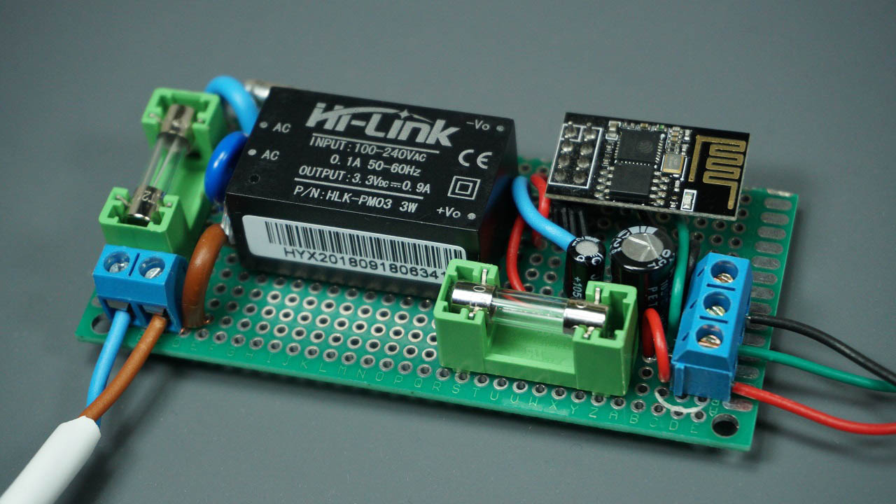
118277


and here is the circuit diagram.
118278


If there is anyone who can help in this regard I would appreciate it. I will share any upgrades as I go along.

Thanks.... ;)
 
Welcome to ETO!

The HiLink module provides 3.3V only. Do you really need the circuit to accept a 5V input?

What will unlatch the circuit?
There is another part number that allows you to select a 5v, however that is not a requirement. Correct me if I am wrong but 3v3 is the normal today.
 
In response the the latching circuit:

Let's assume that all other requirements are met and we are focusing on the latch circuit. The latch circuit will received a 3v3 signal or it could be just as be a soft button. Press and release the button and the circuit latches to ON state. The button can be pressed and released again then the circuit latches to OFF state. This is what I require the circuit to do.

I need someone to design this circuit and also to include a Photo Triac with snubber components seeing that we are switching a Motor on and off. I would like the rating of the PhotoTriac to be rated between 400V and 600V for 3 phase motors as well. Current draw probably up to 30Amps.

I hope this explanation has provided you sufficient information. If anything is unclear please shout. :)
 
To summarize:

3.3 V power source

Toggle flipflop with pushbutton. Output drives a SSR
(Solid State Relay, either purchased or grown with an optocoupler and TRIAC)

SSR drives 120 Vac motor, 3 hp
That is over 2 kW - are you sure about the rating? What is the motor voltage?
If it really is 3 hp, strongly suggest purchasing a SSR. They are expensive or a reason.

External 3 V signal also can set the ff to the ON state
Can the external signal also turn off the motor?

yes / no?

ak
 
Most SSRs have a minimum input voltage requirement of 3 V at 10 mA or so. Getting this from a 3.3 V circuit is cutting it close. I recommend moving the circuit up to 5 V or 12 V. The flipflop and driver circuit will not care.

Most small switching power supplies have a minimum load requirment to stabilize the magnetics. A 3 W supply is overkill, and might have a problem at your very low load current. Suggest moving to a smaller supply.

ak
 
SSR drives 120 Vac motor, 3 hp
That is over 2 kW - are you sure about the rating? What is the motor voltage?
If it really is 3 hp, strongly suggest purchasing a SSR. They are expensive or a reason.

Here is South Africa the single phase voltage is 230v and ~400v three phase. I am speaking under correction on exact voltages brain is tired.
Here is the link to the voltages per country. https://www.worldstandards.eu/three-phase-electric-power/

Motor spec below is for a Toolmate dust collector

Motor Power2200W
Voltage230V

For the JET dust collection the details are as follows:
JCDC-3 Cyclone Dust Collector Kit, 3HP, 230V
 
Most SSRs have a minimum input voltage requirement of 3 V at 10 mA or so. Getting this from a 3.3 V circuit is cutting it close. I recommend moving the circuit up to 5 V or 12 V. The flipflop and driver circuit will not care.

Most small switching power supplies have a minimum load requirment to stabilize the magnetics. A 3 W supply is overkill, and might have a problem at your very low load current. Suggest moving to a smaller supply.

ak
Hence then the power input can be then 5v if need be. But I need EE's here to assist in building this circuit. I appreciate your reply but talking about it does not help me. Show by way example and we can interact as we go along. ;)
 
Can the external signal also turn off the motor?

yes / no?

ak

I am not sure how to answer that but let me try. The whole point of having the circuit is to do just that. Switch the motor on or off by a software switch meaning a physical switch or by way of remote control. I prefer the latter.
 
Last edited:
The "dust collector" may already have the contactor and protection for the motor sotit's best to use that.

The coil henerally has a low voltage and current requirements, so you interface there.

Motor loads are handles by "motor starters" which avoid nuscense trips. Old style use "thermals" which heat from the currents of each phase. They a spring loaded movable gear in a low-temperature alloy. urrent-time behavior causes these to trip. Short circuit protection is done with a fuse.
 
1) I agree with KISS about using the motor's contactor. Does it have one?
2) I have concerns about safety with the proposed setup. Pulse-for-on, pulse-for-off latching circuits can start up in a random state unless precautions are taken to prevent that. 2kW of mechanical power can do a lot of damage, so you wouldn't want the motor to start up unexpectedly. And with remote operation how would you ensure that conditions were safe for start-up (e.g. no child fiddling with the machinery, cat stuck in the air duct etc)?
3) Does the motor come with any slow-start/ramp-up control circuitry?
 
1) I agree with KISS about using the motor's contactor. Does it have one?
Dont know
2) I have concerns about safety with the proposed setup. Pulse-for-on, pulse-for-off latching circuits can start up in a random state unless precautions are taken to prevent that. 2kW of mechanical power can do a lot of damage, so you wouldn't want the motor to start up unexpectedly. And with remote operation how would you ensure that conditions were safe for start-up (e.g. no child fiddling with the machinery, cat stuck in the air duct etc)?

That's why I need a professional to design the circuit

3) Does the motor come with any slow-start/ramp-up control circuitry?
Don't know, but doubt it
 
Look at his video with Dust collection. The unit is mounted on the wall with remote as well.
You will understand then how the whole setup should work.

 
In a commercial dust collector, the wireless remote is only a part of the system. Each tool becomes a part of the system as well. The dust system come son when the first tool turns on. It says on for a time after the tool is shut down, during that time one is presumably heading to a different tool.

Dampers can shut and you can shut and open and you can also have a bypass damper. Interlocks would also exit in the system.
 
Me & the wife are hobby woodturners, and I'm an industrial electrician.
The only time I see motors that dont have contactors to start them are when theres either a variable speed drive or soft start used.
If I was to do this I'd use a 240v coil contactor (or 110 if thats your supply) and control it with either a opto triac and a triac, or with such a small contactor you might be able to just use a opto triac to turn it on/ff, then drive the Led in the opto from your logic level via a resistor.
 
24 VAC might be used too. In the US, control is usually 120 VAC. PLC applications would use 24 VDC.
In the motor starter, there is usually a transformer that is multi-tapped for 440, 460, 208, 240 or just twp that creates a little bit of 120 VAC for control.

24 VAC is used exclusively for air conditioners. At least that was the old way. 16 VAC fir door bells.

Power limited or class II wiring is often used so you don't have to use conduit.

We don;t know what part of the world your in.

The only time I see motors that dont have contactors to start them

There are "contactors" and "motor starters". 3 phase would usually have a motor starter. 3 phase protection is often employed if for some reason the system looses a phase. protection might cost an additional $100.00 USD. I used stuff from Symcomm and was very happy with it.

When you have a bulding wide single phase failure, you react. There were 36 heat pump motors, but they were affected minimalyy. there was a $5,000 cryogenic compressor and a >$5,000 USD roots blower that got protection. We used the thermal on the roots blower.
 
24 VAC might be used too. In the US, control is usually 120 VAC. PLC applications would use 24 VDC.
In the motor starter, there is usually a transformer that is multi-tapped for 440, 460, 208, 240 or just twp that creates a little bit of 120 VAC for control.

24 VAC is used exclusively for air conditioners. At least that was the old way. 16 VAC fir door bells.

Power limited or class II wiring is often used so you don't have to use conduit.

We don;t know what part of the world your in.


There are "contactors" and "motor starters". 3 phase would usually have a motor starter. 3 phase protection is often employed if for some reason the system looses a phase. protection might cost an additional $100.00 USD. I used stuff from Symcomm and was very happy with it.

When you have a bulding wide single phase failure, you react. There were 36 heat pump motors, but they were affected minimalyy. there was a $5,000 cryogenic compressor and a >$5,000 USD roots blower that got protection. We used the thermal on the roots blower.

Mr K.I.S.S. or is it Mrs,

I am getting rather annoyed with your replies. Your are NOT a most helpful member. You have not contributed anything but babbel, no solution nothing to go by to assist in this matter at all. I am beginning to think you are more interested in getting your replies up to increase your member status. Please do not return here unless you have something tangible to contribute. I would encourage you to prove me wrong and provide a solution.
 
Status
Not open for further replies.

Latest threads

New Articles From Microcontroller Tips

Back
Top