I got to make this school project.
This is how should it work:
I need to make circuit that will on every fifth impulse (f=1Hz) that I bring on entrance turn off LED which is located at output. When sixth impulse comes to entrance it must turn on LED and repeat that all over again.
Here is what i think how should i solve this problem:
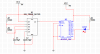
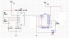
I will use IC NE555 for generation impulses of 1Hz. Then i will bring that signal on Counter and after counter i will put divider. I will connect LED at outputs of divider so when 5th impulse comes at entrance it will turn LED off and when 6th impulse comes at entrance it will turn LED on again.
So its: 555->Counter->Divider->LED
Will this work ?
This is how should it work:
I need to make circuit that will on every fifth impulse (f=1Hz) that I bring on entrance turn off LED which is located at output. When sixth impulse comes to entrance it must turn on LED and repeat that all over again.
Here is what i think how should i solve this problem:
I will use IC NE555 for generation impulses of 1Hz. Then i will bring that signal on Counter and after counter i will put divider. I will connect LED at outputs of divider so when 5th impulse comes at entrance it will turn LED off and when 6th impulse comes at entrance it will turn LED on again.
So its: 555->Counter->Divider->LED
Will this work ?
") with a better explenation.
with a better explenation.