Continue to Site

Welcome to our site!

Electro Tech is an online community (with over 170,000 members) who enjoy talking about and building electronic circuits, projects and gadgets. To participate you need to register. Registration is free. Click here to register now.

  • Welcome to our site! Electro Tech is an online community (with over 170,000 members) who enjoy talking about and building electronic circuits, projects and gadgets. To participate you need to register. Registration is free. Click here to register now.

How can i make this counter stop until I press the start button again

Status
Not open for further replies.

RoyCone

New Member
counterbreadschem.png

counterschematic.png


countertoschem.png

This circuit is from make electronics esperiment 19 page 185. It automaticaly counts from 0 to 9 and is supposed to stop when pressing the stop button and waits until the start button is pressed again to continue counting.

It works but the stop button only works while being pressed which makes the start button useless.

Now, the top 555 is a bistable timer, it's supposed to be off and i turn it on by pressing the stop button and off by pressing the start. It's connected to the stop counting pin 2 of the 4026 chip. If the pin 2 is low then the chip starts counting, so that explains why it starts as soon as the power is on, but if i press stop then it's supposed to go high and stay "stopped", why does it starts as soon as I let go of the button?

I have a logic probe that i have just used for the first time and i've put it on the pin 2, it's low when counting and when i press the stop button it goes high, but doesn't stay high. It turns low in the same amount of time as the counting. Is there a connection with the lower 555 chip that turns it low automatically? Or is it that the upper 555 chip is in monostable mode, but this is bistable right? It's suppose to stay on.

How can I make the counter stop by pressing the stop button and make it wait until I press the start button?
 
Last edited:
Can't help you without a schematic of your complete circuit.
 
You are trying to build a state machine, which can be done with analog
components, but simple with programmable parts, like Arduino.

This is simple implementation of the button logic in code. mBlock takes
your block configuration and converts it to Arduino code and programs
the Arduino. In this case you could use a ATTINY85 as well.

1657621896531.png


You would use an Arduino board. Or Use an Arduino board to program the ATTINY85.

Lots of fun, kids using it in 6'th grade to program robots.

Nano board :

1657622049576.png

1657622083962.png


Regards, Dana.
 
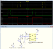
My simulation (below) of the top 555 latch works properly, so I would double check all the 555 connections for a possible error.

1657635671021.png
 
You are trying to build a state machine, which can be done with analog
components, but simple with programmable parts, like Arduino.

This is simple implementation of the button logic in code. mBlock takes
your block configuration and converts it to Arduino code and programs
the Arduino. In this case you could use a ATTINY85 as well.

View attachment 137802

You would use an Arduino board. Or Use an Arduino board to program the ATTINY85.

Lots of fun, kids using it in 6'th grade to program robots.

Nano board :

View attachment 137803
View attachment 137804


Regards, Dana.
I know there are a million different ways to do this, but I am wondering how to do it this way...
 
I know there are a million different ways to do this, but I am wondering how to do it this way...
Roy my post was just for future possibilities. Its a lot easier, because of tools, to work
with processors these days. And after all almost everybody has been programming
since grade school, eg. the use of a 4 function calculator, ones brain is doing programming
on the fly. Use of memory for a variable, sequence of operations, types of operations.....
There are visual tools like mBlock, tools that take a flow chart and convert to code, flow code.
Many variations of graphical tools these days. Even parts that look like a bucket of chips + wires +
protoboard available, all on/in one chip.

Regards, Dana.
 
When you say "works properly", does how long does the stop button, stops the counter?
Until the Start button it pushed.
The circuit acts like a latch that stays in one of its states until triggered to the other state.
 
My simulation (below) of the top 555 latch works properly, so I would double check all the 555 connections for a possible error.

View attachment 137806
I have been thinking and i think the problem is in how I use my tactil switch or maybe that i use the wrong ones or something. I did some experiment and it does change if i wire them differently. I know you prefer schematics but I don't know how to them for different type of switches. I took a picture of my breadboard though... I'm sure you know them. They have two pins on each side of the breadboard. I tried to make the picture as clear as possible. Is it the right way to use those switches in this circuit? If i plug the wire on opposite side of the switch, the start button adds to the counter everytime it's pressed and the stop button does nothing....
20220713_175102.jpg
 
Last edited:
Use your ohmmeter to insure you are getting key closures you expect.


Regards, Dana
They don't latch so that means it's normal for the stop button to work only when pressed, but I can't figure out the use of the start button? Plus it doesn't make sense because the upper 555 timer is supposed to be bistable so it's supposed to latch and stay high
Edit: Check my post below, the digital probe changes How my circuit acts!
 
Last edited:
Try these changes.
Remove one resistor, then connect two 4.7k resistors as shown below.

View attachment 137813
I did the change and it still not working properly. I plug the power in and it starts counting automatically and it stops only when the stop button is pressed. I even rebuild the circuit one chip at a time( meaning I checked with a led how the timer acted and they work fine indivually, the top 555 lights the LED when the button is pressed and goes off when the other button is pressed, the bottom 555 blinks and i plugged the outputs in the 4026, but i still have the same results...
I wonder how "crutschow" has it working, but i'm just a beginner so i have trouble understand his schematics.
Maybe that's how it's supposed to work but I highly doubt it...
Edit: Check my post below I found something!
 
Last edited:
My simulation (below) of the top 555 latch works properly, so I would double check all the 555 connections for a possible error.

View attachment 137806
Okay, hear me out! I saw that the duration of your V(out) lasted only 2 second, so i went to check with a digital probe if the same happened with my circuit, because the pulses last 8 seconds and I thought maybe the top bistable 555 worked correctly inside the 8 second pulse from the bottom astable timer and the problem was at 8 happening at second. So I placed the probe on the pin 2 of the 4026 and for I don't know what reason the whole circuit worked!! (meaning I press the stop button once and it latches and the counter stops counting) but then I remove the probe and it doesn't work anymore...(meaning the counter stops only when the stop button is pressed, it doesn't latch)
Do you have any idea what is happening?

NB.: There are two alligator claws on the probe that I attach to the positive and negative side of the power source of the circuit
 
I saw that the duration of your V(out) lasted only 2 second
That's because that was a convenient simulation period I used.
The 555 will stay in either state indefinitely (hours, days, years, as long as it has power) until it receives a PB signal to change states.

Below is the simulation for 2000 seconds, and there is no difference in the 555 operation:
I could do the simulation for a zillion minutes, and it would still operate the same.

1657841230760.png
 
That's because that was a convenient simulation period I used.
The 555 will stay in either state indefinitely (hours, days, years, as long as it has power) until it receives a PB signal to change states.

Below is the simulation for 2000 seconds, and there is no difference in the 555 operation:
I could do the simulation for a zillion minutes, and it would still operate the same.

View attachment 137843
Okay well if you were troubleshooting, what would you do? I know that if I unplug the wire at pin 2 from the 4026 counter it stops counting and if i plug it back in, it starts again. I placed a LED to check if the 555 is on or off and it doesn't matter if the led is on or off the 4026 counts the moment it's pin 2 is connected to the pin 3 of top 555...
 
Last edited:
I placed a LED to check if the 555 is on or off and it doesn't matter if the led is on or off
Is there a resistor in series with the LED to limit its current?

Remove the LED and measure the output voltage of the 555 after you've pushed the start button, and after you've pressed the stop button.
 
Status
Not open for further replies.

Latest threads

New Articles From Microcontroller Tips

Back
Top