Electro Tech is an online community (with over 170,000 members) who enjoy talking about and building electronic circuits, projects and gadgets. To participate you need to register. Registration is free. Click here to register now.
Welcome to our site! Electro Tech is an online community (with over 170,000 members) who enjoy talking about and building electronic circuits, projects and gadgets. To participate you need to register. Registration is free. Click here to register now.
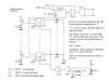
I can think of many ways to do this. Here is a simple design that can expand to any number.
In the unlikely event (but possible) of more than 1 button pressed within some nS from each other, the circuit could be modified as in the 2nd diagram. Here the extra transistor monitors the current to the LED's and any current higher than that for 1 LED will reset all the flip-flops. Because all switches have some contact bounce lasting (~10mS), after a reset pulse by the transistor one of the switches should be able get a valid set in this time. R10 will be calculated based on the LED current and Vb-e (worst case) of the transistor.
You can also do it with SCR's and lamps quite easy.
Yes, now I see it. Missed that connection the first time as I was too busy looking to see which lines connect and which not. On my screen it is not easy to see as the dots are so small.
One word of caution though :!: The lower comparator may exhibit normal turn-off delays of several uS (as long as 10uS according to National's datasheet) due to the storage time in this comparator (no spec given for upper comparator). This together with the propagation delay (~0.5uS) of the internal flip-flop which drives the discharge transistor (~30nS after pin 3) to operate the lockout, makes the probability of having more than one led to come on much greater with more stations added. For this very same reason monostable circuits with output pulses shorter than 10uS are not recommended for the high risk of re-triggering.
The ic is not being used as a monostable, so considerable overdrive is available. Under such conditions the propagation delay from trig to output
is ~200nS. While a spec for the threshold input is not given, considering that this is the npn comparator I would expect that it is at least as fast.
I never said your's is a monostable, my whole point is that, the possibility exists for more than one LED to be activated even if your delay is only 100ns or shorter. You should have a way to deal with this.
The design posted by srineo173 deals with it by selecting the highest of the triggered numbers. My circuit reset in such an event. I ran a simulation on your circuit with only 2 stations and had no problem getting both leds triggered. In the simulation I fired the 2nd switch from 100~800nS after the first switch and got both LED's on. I also modified my first circuit after doing the same test that confirmed this problem. Your circuit could be easily modified as well.
I am not slamming your design, only pointing to lurking problems that are not so obvious.
EDIT:
I took another simulator with a industry spice model and simulated the delay from threshold trigger (8v) on a 12V system to the point of lockout on this line (<8V) by the discharge line. The result shows a figure very close to the delay quoted by National (~470nS). I made the rise time of the trigger pulse on TH very fast 1nS to get a accurate reference line.
I use 2, Proteus and Protel. The one above was done on Protel (I think it is more accurate) and most of the ones in my other posts with Proteus. Proteus is nice cause you can debug and run uP circuits as well. You can download a student version of Proteus from http://www.labcenter.co.uk/
I see that FRIED posted a 555-based quiz buzzer. I would like to clarify where the connections are. From the schematic of the buzzer ciruit, it looks as though pin-7, C1 and R1 join to the 33K-line side of the 0.01uF cap on pin-2. I also think that the 0.01uF cap connects directly between pin-2 and the 33k-line, without connecting to the 10K-line which the schematic shows it crossing. I don't know - I don't think so, but I don't know. It's also a bit mystifying with the apparent common connection to the -ve (GND) for pin-1, one side of the buzzer and the -ve side of C1. I think this is supposed to be there.
Similarly on the switch circuits it looks as though there is a common connection between pin-6, pin-7, the 100k and the 33k-line. Or is this wrong. Maybe pin-6 is connected to the 100K and pin-7 is connected to the 33k-line. As per the buzzer circuit, I take it that the connection from pin-2 only connects to the 10K-line and not the 33k-line.
It would help to have big fat dots on each cross-connection to make it clear. Would you be able to provide a more clear circuit schematic please?
True though that may be, I fear it would take me quite a while to track down that particular book (in Oz). The 555 circuit appears to have considerable merit, but I just need clarify the connections on the IC as they are not readily apparent on the schematic provide.
This thread is over a year old. You would be more successful if you started your own thread. Furthermore, I don't understand what you are trying to ask. Since your location is not filled in I must just assume that English is not your first language (since your writings don't make any sense). You should try to compose your question a little more clearly in your own thread. Good luck.
This site uses cookies to help personalise content, tailor your experience and to keep you logged in if you register.
By continuing to use this site, you are consenting to our use of cookies.