Continue to Site

Welcome to our site!

Electro Tech is an online community (with over 170,000 members) who enjoy talking about and building electronic circuits, projects and gadgets. To participate you need to register. Registration is free. Click here to register now.

  • Welcome to our site! Electro Tech is an online community (with over 170,000 members) who enjoy talking about and building electronic circuits, projects and gadgets. To participate you need to register. Registration is free. Click here to register now.

I need a quiz buzzer/light system circuit please

Status
Not open for further replies.
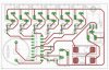
I can think of many ways to do this. Here is a simple design that can expand to any number.

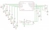
In the unlikely event (but possible) of more than 1 button pressed within some nS from each other, the circuit could be modified as in the 2nd diagram. Here the extra transistor monitors the current to the LED's and any current higher than that for 1 LED will reset all the flip-flops. Because all switches have some contact bounce lasting (~10mS), after a reset pulse by the transistor one of the switches should be able get a valid set in this time. R10 will be calculated based on the LED current and Vb-e (worst case) of the transistor.

You can also do it with SCR's and lamps quite easy.


Can u tell me how to exactly calculate the value of the R10 resistor
 
R10 is calculated so the current of one LED will not turn Q3 on, and the current of two LEDs will turn it on. If the voltage is 12.0V, the resistors R8 and R9 are 470.0 ohms, the LEDs are red with 1.80 volts drop, and if the 4013 has 0.1 volts loss under load, then current in one LED will be approximately 21.5mA. If you choose 400mV for one LED and 800mV for two, then R10=0.4/0.0215 = 18.6 ohms. This assumes Vbe of Q3 is approximately 0.65V which is typical at 25c.

Note that all devices have tolerances which I have ignored. The good news is that R10 and Q3 are needed if two buttons are pressed within microseconds of one another.

The circuit might not work, however, since it depends on the 4013's D inputs being faster than the CK inputs. All D inputs should be tied to the top side of the push buttons.

Hopefully no one has had trouble with this in the six years since this circuit was posted.
 
Hi. I hope everyone is still reading this thread. I would just like to ask if the first circuit shown in the thread is working properly. We have an upcoming quiz bee this September and I am assigned to make a 8 switch buzzer. I would also like to ask if there is any modifications made from the first circuit?

Thanks....
 
Sorry I was not able to hold a copy of the pic version. Do you still have the circuit or maybe the link of your post?bthank you for the reply.
 
I never posted it, as I built it much after the post thinking it would be a fun project for the kids. I will look for it. It required a mod (jumper or resistor I think) somewhere if I recall. We had a blast with it, then I gave it away (it had a bunch of cords and buttons on the end, so it did not store well. I will look for the SCH/PCB (done in Eagle) and the HEX. If I find it I can zip it and email it to you. If it looks OK, I will post it here. I did it in a rush just to do it. Mind you this was some time ago, but if I still have it you are welcome to it.
 
Last edited:
Here is the board. Very simple with a microcrontrller. You will need to download Eagle CAD. I will look for the software and send the source and HEX. It uses a newer PIC so that is a good thing. You will need to get a PIC and program it. No promises, but if I find the code and after I see a picture of your board made, I will (for a small fee; chip and shipping) dig out a programmer and burn a chip for you if you can not get a programmer or someone to burn one for you. If nothing else this will give you a head start on the project. We had a blast with it, I played the host to the kids and wife. I just did a board for a fellow in another thread, since I had not done a board in some time. Just to keep the homemade skills up.
 

Attachments

  • new95.jpg
    new95.jpg
    163.9 KB · Views: 1,172
  • new96.jpg
    new96.jpg
    53 KB · Views: 950
  • gamebuzzer.zip
    50.5 KB · Views: 316
Woah! thank you. Is it possible to use a PIC 16F877/16F877A as an alternative for the pic you just posted. Because the PIC 16F877A is commercially available here and we also have a programmer in school for 40 pins.

If ever it is possible to use 16F877, is there a difference of pin functions between the two?
 
Looks like I made one in 6/2006 and did the code with Mikroe BASIC (free download of MikroBASIC). We liked it a lot. It had hard soldered buttons on the 2006 board and it did not store well. In 1/2007 it looks like I made a version we could unplug the buzzer buttons/cords. Anyway, it is what it is and if it helps great. Not looking to make another one, the kids are a lot older now and all drive cars :D Did not look at the code, may not even have comments. Basically you have 7 controllers, 6 for the player, 1 for the host to start the countdown. PM if you have a question or two. You will need to make controllers. I had PVC pipe handles with momentary switches in the tops.
 

Attachments

  • gamebuzzer.zip
    2.3 KB · Views: 229
Last edited:
Woah! thank you. Is it possible to use a PIC 16F877/16F877A as an alternative for the pic you just posted. Because the PIC 16F877A is commercially available here and we also have a programmer in school for 40 pins.

If ever it is possible to use 16F877, is there a difference of pin functions between the two?

Well, if you are in school and have a programmer, I would think this would be a good project. If you change the device type in the compiler and the chip in Eagle, and re-layout the board due to the 40 pin chip. You have the source code, the schematic and free programs on the net (Eagle Cad and MikroBASIC), so anything is possible. Since you stay the in Microchip family it should be a simple task. With all the pins on the 877, you can move the LEDs to separate output as well. Then you do not have to toggle the button (inputs) and led (outputs). From what you have, a few students should be able to clean it up and modify it. The thing would be a lot of fun with friends. Post your changes for others. Other seem to want this. I ad PMs about it for a bit. Was shocked the thread showed back up.
 
jezer,

For a simple, infinitely expandable (theoretically) Jeopardy game circuit you might look at this site: Game Circuits
I've built several versions.

Ken
 
Here is the board. Very simple with a microcrontrller. You will need to download Eagle CAD. I will look for the software and send the source and HEX. It uses a newer PIC so that is a good thing. You will need to get a PIC and program it. No promises, but if I find the code and after I see a picture of your board made, I will (for a small fee; chip and shipping) dig out a programmer and burn a chip for you if you can not get a programmer or someone to burn one for you. If nothing else this will give you a head start on the project. We had a blast with it, I played the host to the kids and wife. I just did a board for a fellow in another thread, since I had not done a board in some time. Just to keep the homemade skills up.

Nice job mramos, I've copied the files as I'm looking for such project with thanks.

One question please, Instead of the input jacks x1 - x7 ( If I recognized them correctly), can I use push buttons ? if the answer is yes, shall I use Normally Closed as I guessed from the schematic?

Thanks
 
Nice job mramos, I've copied the files as I'm looking for such project with thanks.

One question please, Instead of the input jacks x1 - x7 ( If I recognized them correctly), can I use push buttons ? if the answer is yes, shall I use Normally Closed as I guessed from the schematic?

Thanks

Yes, the original was two pad to solder the buttons (momentary switches) too. I added the jacks to disconnect the wired buttons so it would store better than wrapping 7 wires and pvc pipe handles around the PCB. The board posted requires a mating plug, two wires and momentary button (times 7). Number 7 button is for the host to start the games, do not recall the countdown, but should be in the .bas file. You can change it about anyway you want. Sure the code is probably nasty, but it was a just make it work so we can play.
 
Quiz circuit

i will do this circuit with 16F778A but i need it to be more complex with sound.
I mean when the answer is wrong to sound differently compare to when it is right.
 
Go to post #29. unZip the attachment. Extract the .bas file.

Ken
 
Status
Not open for further replies.

Latest threads

New Articles From Microcontroller Tips

Back
Top