Electro Tech is an online community (with over 170,000 members) who enjoy talking about and building electronic circuits, projects and gadgets. To participate you need to register. Registration is free. Click here to register now.
Welcome to our site! Electro Tech is an online community (with over 170,000 members) who enjoy talking about and building electronic circuits, projects and gadgets. To participate you need to register. Registration is free. Click here to register now.
When it is daylight I want the circuit to work normally. When it is dark I need the circuit to be disabled so I think I need to have a LDR in series with my logic line.
What you dont want is a situation where the LDR is half way between light and dark where that biases the PFET into a state where it is half on/half off as that might cause excessive dissipation in the PFET. I would feed the LDR into a comparator (LM3xx type) to create Light/Dark logic level which is combined with the "logic Signal" in an AND gate. If "logic Signal" comes from a uController, then feed the LDR comparator into an input pin and do the "AND" in software.
Hi Mike ... I am physically at limit in the box so I am stuck with looking for a simple hardware solution. I was hoping that I could use the LDR with another transistor to either run the logic signal through to control Q1 or perhaps disabling it by lifting the ground?? (without destroying it).
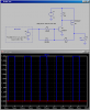
This is the high side switch you gave me and I found a smaller footprint PFET that works quite good and can carry 6 amps.
What are the specs for the LDR? Dark resistance, Fully illuminated resistance? Resistance at the illumination level where you want it to enable the driver?
What is the nature of the load connected to the drain of the PFet?
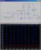
Here is a 6A switch which turns the load ON only if the LDR resistance is ≤ 75KΩ. It is OFF whenever the Port pin is Low(diode). It has positive feedback so that the dissipation in the FET is minimized as the LDR slowly changes resistance.
This site uses cookies to help personalise content, tailor your experience and to keep you logged in if you register.
By continuing to use this site, you are consenting to our use of cookies.