Continue to Site

Welcome to our site!

Electro Tech is an online community (with over 170,000 members) who enjoy talking about and building electronic circuits, projects and gadgets. To participate you need to register. Registration is free. Click here to register now.

  • Welcome to our site! Electro Tech is an online community (with over 170,000 members) who enjoy talking about and building electronic circuits, projects and gadgets. To participate you need to register. Registration is free. Click here to register now.

How to turn a TEG output into something I could use?

Status
Not open for further replies.
Looks good. :cool:

But the OP does not want to use 2 cells.

spec
 
Last edited:
upload_2016-7-8_7-55-19.png

One idea for the single cell project.
The "SW" is set to turn on at 1.7V and off at 1.0V.
Boost maximum is 1.75V Probably should be set to 2V.
Not running exactly at "max power point" but close. It will take many more parts to run exactly at max power.
 

Attachments

  • 3526L-2TEC switch.asc
    1.8 KB · Views: 204
View attachment 100350
One idea for the single cell project.
The "SW" is set to turn on at 1.7V and off at 1.0V.
Boost maximum is 1.75V Probably should be set to 2V.
Not running exactly at "max power point" but close. It will take many more parts to run exactly at max power.

You are a clever chap Ron :cool:

spec
 
Some time I should find out what you do. (off line) I think we have much in common.
Many time while I slowly type your post the answer. LOL

Off to work I go.
Same here-:) I'm retired, but miss some parts of work, but not the politics and procedures, meetings and reports, BS and appraisals...:eek:

spec
 
One idea for the single cell project.
The "SW" is set to turn on at 1.7V and off at 1.0V.
Boost maximum is 1.75V Probably should be set to 2V.
Not running exactly at "max power point" but close. It will take many more parts to run exactly at max power.

If the OP could be persuaded to use an MCU, MPP could be implemented and the motor could be turned on and off by the MCU too.

spec
 
Here is another offering:

Issue 20 of 2016_07_09

2016_07_08_TEG_SMPS_Ver1_NOTIONAL.png
ERRATA
(1) Change R1 to 1M (standard value)
(2) Change R2 to 502K (500K will do) to set out put voltage to 4V
(3) Change L1 to 20uH to improve efficiency and start up
(4) Delete Cff (not necessary to reduce ripple)
(5) Initially make RMPCC 47K (see note below about MPP resistor selection)
(6) Delete the word 'Notional' from title along lower schematic

NOTES
(1) The stir motor controller of post #54 connects to the 4V output supply to give the required motor on and off periods (energy in = energy consumed by system + margin). Alternatively micro-controller unit (MCU) could be used to allow practically unlimited control of the motor.
(2) The CP1654A2 battery is a LiIon 100mA/h rechargeable button cell, but battery capacity can be chosen to suit requirements.
(3) The LTC3105 minimum input voltage (in the above configuration) is 250mV
(4) The LTC3105 has MPP control. RMPPC to be selected to optimize power extraction from the TEG when the circuit is tested in the operating environment
(5) All capacitors are through-hole ceramic with X7R dialectic (not surface-mount), +-10% or better.
(6) All leads must be as short as possible
(7) All current carrying conductors (wires and PCCT traces) must be substantial
(8) All capacitors must be physically connected as close to the chip pins as possible
(9) All resistors are through-hole +-2%, or better, 250mW (quarter Watt), or higher, metal film type

DATA SHEETS
(1) LTC3105 (£4.00UK from DigiKey)
http://cds.linear.com/docs/en/datasheet/3105fb.pdf
(2) LTC3105 Demonstration Board
http://cds.linear.com/docs/en/demo-board-manual/dc1587f.pdf
(3) Varta CP1654A2 LiIon Battery
http://www.varta-microbattery.com/applications/mb_data/documents/data_sheets/DS63165.pdf
 
Last edited:
Ron and Spec, that is amazing. I still need to understand what you guys did there and it will take me a couple of hours (at least) but this is all I'm doing today :)
I'll be back with questions...
 
Ron and Spec, that is amazing. I still need to understand what you guys did there and it will take me a couple of hours (at least) but this is all I'm doing today :)
I'll be back with questions...
No probs Matienzo. :)

spec
 
That is an interesting part.
By using a 51k resistor on MPPC I can set the max power point very well. It does the same thing that I did to get more power out of the cell but allows one to set the point. I know the other part so well I know I could trick it into doing MPPC but here it is programmable.
upload_2016-7-8_19-3-1.png


The LDO output is very interesting. It looks like I can get a higher voltage on LDO then Vout. Who would have thought of that. (low current only)

It is probably possible to use the pgood pin to turn on the motor. Have not thought about that yet.
 
Hy Ron,

So you like the LTC3105.:cool: There are some more harvester chips that I am looking at.

Should C1 above perhaps be a high capacity super cap as you previously mentioned to form the energy store and provide the start current for the motor?

I wonder if starting and stopping the motor fairly rapidly would be a bit inefficient due to the motor start up losses. Also, I suspect that running a 6V motor at such a low voltage isn't going to be too efficient and may lead to problems on a production run and through the life of the milk stirrer.

The battery approach does not have this problem.

Also with the battery approach the circuit can be harvesting energy 24/7 even when stirring is not required. For this reason it may be better to go for a larger battery (CR123 rechargeable) but you have the flexibility to choose whatever battery capacity suits.

You can also stir the milk with no heating, for a period that is.

The LDO output must be programmed to less than Vout.

Are you planning on using the LDO output?

spec
 
Last edited:
C1 could be 0.22F or 0.47uF. See my post #40.
The reason I chose a very small cap is SPICE takes a week to simulate. So I use a small cap and just know that 100x is 100x. What I am saying is a small cap (100uF) might cycle in 0.1 seconds and we know 100x bigger is 100x longer.
--------------
Back in #40 I suggested turning the motor on at 1.7V and off at 1.0.
If we let the supper cap charge to 5V or 3.3V and then use a 8 pin buck IC, with little to no filtering, a much smaller cap can be used. The motor will be heald at 1.5V with no ripple.
I don't know which is best.
 
Last edited:
Here is a stir motor motor controller:

Issue 20 of 2016_07_10

2016_07_10_iss3_ETO_STIR_MOTOR_CONTROLLER_VER1.png

ERRATA
(1) Fit a switch in the 4V supply line from the energy harvester to switch the stir motor controller on and off

NOTES
(1) This circuit connects to the 4V and 0V output power lines from the energy harvester circuit of post #47
(2) This circuit continuously turns the stir motor on and off.
(3) The on period is set by potentiometer RV1
(4) The off period is set by potentiometer RV2
(5) The on and off controls do not interact
(6) All solid capacitors are ceramic through hole (not surface mount) X7R dielectric, 15V minimum, +-10% or better.
(7) The timing capacitor, C1, is a through hole, solid tantalum type, 15V minimum.
(8) All resistors are through hole, +-5%, or better, 250mW (quarter Watt), or higher, metal film type.
(9) R9 is a gate stopper and should be connected directly to the PMOSFET gate.
(10) D9 is type 1N400x where x = any number 1 to 7

DATA SHEETS
(1) Texas Instruments LMC555 Timer (£jelly bean)
**broken link removed**
(2) Toshiba PMOSFET TPN4R712MD (£0.80UK DigiKey)
https://www.digikey.com/product-det...age/TPN4R712MD,L1Q/TPN4R712MDL1QCT-ND/5323105
(3) Vishay Shotkky Diode BAT41 (£jelly bean)
https://www.vishay.com/docs/85659/bat41.pdf
 
Last edited:
C1 22uF should be 0.22F for 20 seconds of run time and 90 seconds of charge time.
Added a buck. C1 charges from 1.6V to 4.6V and then is bucked down to 1.5V for the motor.
Used a LMC555 to control run/charge time based on how charged C1 is. (MUST BE CMOS type)
LDO is set to 5V.
Points of interest:
1)PGOOD goes high when C1 is charged. Use that as the 'turn on signal'.
2)I think I can find a version of U2 that has a PowerGood pin that will go low when the duty cycle cycle reaches 100%. This wold make a 'turn off signal'.
3)LMC555 makes a good flip flop. But in this case the out put is inverted from what I want. (Could use 8-pin PIC micro)
4)I planed on using LDO voltage to set a level for 'turn off'. The LMC555 does that at 1/3 of LDO.

upload_2016-7-10_6-44-49.png

upload_2016-7-10_6-47-46.png

I learned some. Probably time to move on.
 
Hi Ron and Spec, thank you so much for helping me out. I started reading on the datasheet after someone in the chat suggested it and I'm still not sure what to ask. I feel like the pointy hear boss :)
For what I can gather the last circuit design looks like a conciliation of the ideas you guys bounced around.

I'll put it together today if I can find all the parts in my local electronics store but I have some question about names and connections.
The connection among the 555 OUT, LTC3549 run and mode has a MOSFET? What type exactly? I have a couple but I'm not sure if they will be a good fit. I have a l7805cv, irf510, ld33v and lm1085.

There are connections coming out from the 555 and LTC3549 going to LDO and Pgood. Do I connect them directly to the pins labeled LDO and Pgood on LTC3105?
 
There are separate approaches from Ron and me. I can only describe my offering which comprises the energy harvesting circuit of post #47 connected to the Stir Motor Controller of post #54. You must use the components as specified, especially the PMOSFET shown in the schematic of post #54.

spec
 
Last edited:
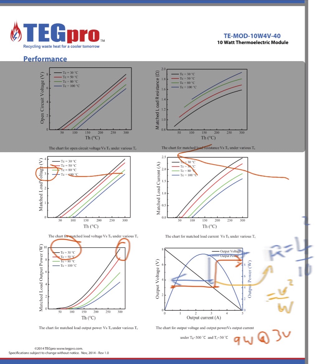
  1. Let's try a different load to see how it changes everything.
  2. Consider 3 x 3W LED' each with some identical transfer function, that looks something like thus
  • <2.85V the current drops off exponentially LED must be kept cool pref << 60'C for longer life 2x for every 10 deg drop in temp rise, (Arhennius Effect)
  • the cold side of the Seeback Thermal Electric Genererator (TEG) wafer also needs to be cool to generate power (useful to share heatsink method with LED alum-clad PCB, if possible) Seebeck Effect.
  • LED current rises = a quasi linear Effective Series Resistor (ESR) above.2.85V for white or blue according to curves in datasheet or my rule, approx ESR= 1/W @25'C such as a 3W LED is 0.33Ω. or **If= (Vf-2.85)/0.33 [A]
  • (quasi=almost),, ESR refers to internal conduction losses which "every" electrical part has...
  • Since 3 LEDs is series ESR's will add or total string of 9W max with ESR=1Ω at ~9V this does not match TEG, so let's try parallel 3 LEDs (same type and pref same batch, thus same ESR, which can have 10% tolerance typ or better or worse, depending on supplier quality (Consider Toshiba) Now we have 9 W load with ESR=0.11Ω when Vf >2.85V
  1. Now examine TEG imperfections and see how rise in cool side T reduces Pmax out, lowers Vout and increases ideal linear load. But LED's are like all diodes nonlinear unless piece-wise approximated as Vf= 2.85V + If*ESR
  2. It is possible to match all these curves into transfer functions and simulate in a spreadsheet
  3. (these may be 3rd or 4th yr fundamentals in Eng non-linear courses or simple math you can put in a spreadsheet)
  4. Maximum power transfer Theorem states this occurs when source and load impedances are same
  5. So basically TEG rises in Voltage until 3V and when light turns on , diode "saturates" ESR is like a voltage regulator to the TEG or a power Zener at around 3V where current that can be supplid to 3 LEDs in parallel matches the load presented (see **)
  6. So an ideal zero loss design would match the power source to the load and have no added lossy parts and is mwchanically cooled and heated by design to satisfy the Rja or junction to ambient thermal resistance of heatsink. I would expect 0.2'C/W CPU cooler might be good for small 4x4 cm Alum substrate PCB with copper traces.
    • For finger poking on iPad design, this is what I suggest. 30AWG magnet wire between LED's on Alum-clad cold PCB with cold side of TEG and hot side differential thermally isolated and only TEG, LEDS, PWB, cooler and wire.
    • Some may suggest adding small R to each LED to balance the current sharing from ESR mismatch e.g. 25% of LED ESR to prevent "Thermal Runaway" but if you have good LEDs, this is not critical as they may be matched to within 0.1% if in same batch. or 1% from similar batches.
  • No DC-DC converter required when load voltage matches voltage source at loaded condition, hence more efficiency
  • 8496092000_1468341117.jpg
 
  • My answer has some advanced concepts which can be applied to any energy transfer system, e.g. ESR, non-linear to piecewise linear conversion, maximal power transfer theorem for voltage sources, and current sinks, heat sink thermal resistance also uses Ohm's Law. etc etc.
  • it was Not written like a thesis paper, more like cut to the chase solutions with fat fingers on an iPad
  • I have not address the mechanical thermal insulation necessary to improve heat source efficiency, but high temp silicone will thermally insulate well near flame or other heat source like a parabolic sat dish reflected onto hotside solar power is 1kW/m2 perhaps only magnifier glass is needed of correct size and losses minimized.
  • For battery storage again matched voltage is best with low cost such as several matched LiPo cells in parallel with 0.6V R drop or DC-DC converter if ambitious using switch mode to charge and discharge or simply limit voltage to 4.2V during charge and limit dishcarge current with added ESR to drop 3.6 to ~3V or use simple oscillator with PWM to pulse LED's for dimmer and reduce average current.
  • there are hundreds of different efficient solutions.. low cost and easy to make, pick any
 
Last edited:
Status
Not open for further replies.

Latest threads

New Articles From Microcontroller Tips

Back
Top