Matienzo
Member
Hello there,
I'm a beginner with electronics so I apologize in advance for my basic questions.
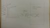
I'm working on a project that uses a Peltier device (TEG) as the power source. The conditions under which it is used allow me to harvest about 1V and 130mA. The motor I want to power on a cycle - off and on with intervals of about 30' or a minute- works using a minimum of 1.5V and ~100mA under the load.
I think that if I could store the electrical energy in something like a capacitor and then release it with the desired voltage and current it could work.
My questions are:
How do I tell the capacitor to release the energy once it is full?
How do I transform the stored energy into a useful, constant output? 1.5v ~100mA
The main constrain: the only power I can use is the power coming from the peltier.
I'm a ME and my knowledge about circuits is rather rustic so I would appreciate if you guys/gals keep your explanations or instructions as basic as you can") Any resources, references, suggestions, ideas or schematics are welcome.
Any resources, references, suggestions, ideas or schematics are welcome.
Thank you in advance!
Paulo
I'm a beginner with electronics so I apologize in advance for my basic questions.
I'm working on a project that uses a Peltier device (TEG) as the power source. The conditions under which it is used allow me to harvest about 1V and 130mA. The motor I want to power on a cycle - off and on with intervals of about 30' or a minute- works using a minimum of 1.5V and ~100mA under the load.
I think that if I could store the electrical energy in something like a capacitor and then release it with the desired voltage and current it could work.
My questions are:
How do I tell the capacitor to release the energy once it is full?
How do I transform the stored energy into a useful, constant output? 1.5v ~100mA
The main constrain: the only power I can use is the power coming from the peltier.
I'm a ME and my knowledge about circuits is rather rustic so I would appreciate if you guys/gals keep your explanations or instructions as basic as you can
Any resources, references, suggestions, ideas or schematics are welcome.Thank you in advance!
Paulo