Continue to Site

Welcome to our site!

Electro Tech is an online community (with over 170,000 members) who enjoy talking about and building electronic circuits, projects and gadgets. To participate you need to register. Registration is free. Click here to register now.

  • Welcome to our site! Electro Tech is an online community (with over 170,000 members) who enjoy talking about and building electronic circuits, projects and gadgets. To participate you need to register. Registration is free. Click here to register now.

How to route EMI2121?

Status
Not open for further replies.

pavjayt

Member
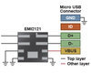
I was suggested to use EMI2121 for EMI/ESD protection of my circuit by Microchip while interfacing with their MCP2210 interface controller. Searched online and have seen this being used in many applications but didnt come across one board design so far. EMI2121 package seems pretty good, but for me, I was not able to figure out how to route the differential USB pair to this package's 1 (D+) and 2(D-) pins without using vias and on the other hand they suggest not to use any vias for USB data lines while using similar length traces. Wish they designed this package in a more board designer friendly way by having Vbus, D- and D+ on one side and corresponding outputs on the other side.

Any suggestions?

thanks
 

Attachments

  • emi2121design.png
    emi2121design.png
    89.9 KB · Views: 194
D1 and D2 can be switched into the chip (USB D1 can go into Input 2- on the chip, and that becomes output 2 on the chip. Both data lines are the same on that EMI suppression chip.
 
Thanks for your reply gophert. My initial thinking was that way, but then looking at online resources related to this chip, I was doubtful. Looking at the pin description and design resources on ON semi website, they are always swapped to actual USB pinout. The pin description specifically says + and - in and outs for the IC. Contacted semi and explained them the issue clearly and was told will get back to me after talking to their engineering team. Will followup with them today.
 

Attachments

  • EMI2121-diagram.jpg
    EMI2121-diagram.jpg
    16.3 KB · Views: 184
  • EMI2121 pinout.png
    EMI2121 pinout.png
    70.2 KB · Views: 171
Look at the chip schematic. Both the same.
 
Followed gophert's suggestion and routed it by swapping the pins. Confirmed with OnSemi as well where they suggested to do the same.

thanks
 
Status
Not open for further replies.

Latest threads

New Articles From Microcontroller Tips

Back
Top