Continue to Site

Welcome to our site!

Electro Tech is an online community (with over 170,000 members) who enjoy talking about and building electronic circuits, projects and gadgets. To participate you need to register. Registration is free. Click here to register now.

  • Welcome to our site! Electro Tech is an online community (with over 170,000 members) who enjoy talking about and building electronic circuits, projects and gadgets. To participate you need to register. Registration is free. Click here to register now.

How to connect transistors in parallel

Status
Not open for further replies.

Nexus-PC

New Member
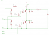
I am working on a flyback circuit. I have 2 transistors hooked up in parallel (the circuit had one originally and works with one or 2). The problem I have is that I am looking for a way too hook them up in series to get higher output. I have read on several sites including this one that hooking them together in parallel will do that for me except that hooking them together in parallel will only up the amperage and not the voltage. I would assume then that hooking them in series will up the voltage and not the amperage. I must add that I am a "newb" when it comes to electronics so try not to get too technical when explaining things to me and please be patient with me. Sorry, the title should say "How to connect transistors in series"
 
Last edited:
You need to be FAR, FAR more specific about EXACTLY what you're trying to do - but 'generally' it's not something you would do, although it's certainly possible under specific circumstances, but each specific problem would probably need a different specific solution.

Basic answer - use a higher voltage transistor!.
 
I can't get more specific than wanting to know how to connect transistors in series, that is very specific. Exactly what I am trying to do is get higher power output. Everything you need to know is in my post, it can't get any more specific than that. Using a higher voltage transistor is not an option in this case, they don't sell much better than what I've got. 2 transistors in parallel will up the amperage but have a lower output voltage so I want to connect them in series which will up the voltage but lower the amperage. It should be as simple as taking them off and wiring them together differently. My assumption, and I could be wrong, which is why I'm here is that I should be able to wire the emitter from one into the collector from the other one and should achieve double the voltage and half the amps but I am assuming that connecting them in series is a little more tricky than that and I don't want to try out of fear of frying my hard to replace parts.
 
Last edited:
Transistors in series is very difficult. I have done it on very large TV sets.
Junction Transistors or MOSFETs?

High voltage transistors (BJT) are slow. They will not turn off at the same time.
 
They're junction transistors, unfortunately MOSFETs won't work for the circuit I'm using. I don't necessarily need them to turn off at the same time In the last hour I found a few diagrams which showed them connected in series emitter to collector with the bases attached together with resistors but none of them listed resistor values.
 
Hello there,


This can be done but how reliable it is might be a little questionable. Each transistor needs the right drive signal, so you have to figure out how you will supply that signal with whatever you have as input. You can not connect the bases together so forget that.

Each transistor also has a voltage rating, and that rating will be much less than the total voltage of course, so a trick is incorporated. A zener across collector to emitter to make sure each transistor voltage rating is not exceeded. And of course that means each transistor voltage rating has to be high enough so the total voltage of all the transistors added exceeds the max voltage of the system.

It's always better to use one transistor so you should try to get one first.
 
What transistors are you using?
What type of 'flyback' are you using? There are more than one type.

I have used 1200 volt and 1500 volt transistors in series. It is very important they turn off at the same time. If one is faster all the voltage will be across it. It will break. High voltage transistors are slow and have a long storage delay time. Even using 1000 volt transistors there could be 1uS difference in turn off time. The faster transistor will die in 200nS, long before the other transistor opens up.

The gate drive circuit is complicated.
 
Here's an ancient example: **broken link removed**

It would still be interesting to know what voltage is needed, NPN or PNP, and the amplifier configuration, if those "unnecessary details" are known.

John
 
It is hard to know what "flyback" means.
We need to know if what he wants is a linear amplifier like John said.
Or a switching power supply run in flyback mode.
Or a high voltage supply like the flyback used in a TV set.
2-PNP or 2-NPN or PNP+NPN?
With out more information we need to stop guessing.

I can't get more specific
 
I am using a TV flyback with a very simple circuit. both of my transistors are BU 4525AX PNP transistors which are pretty high up the line of transistors. They put out a bit more power than the usual 2n variety that people are claiming as the best and the circuit is quieter than circuits using the 2n variety. I am not looking for a specific voltage, I am just looking to get bigger arcs without building a much more complicated circuit for it. I am getting up to 1 inch arcs and I am looking to get at least 2 inch arcs out of it. I could get right into it and start building a MOSFET power supply which I can put a voltage control on so it's not so powerful (they can get up to 5 foot arcs from a MOSFET supply). Like I mentioned, I'm a "newb" and I probably shouldn't have started by building a flyback circuit before other less dangerous things but I like to live on the edge and those arcs in peoples videos really intrigued me to build one.
 
How about let's make it simple like I asked, all I want to know is HOW CAN I CONNECT 2 OR MORE TRANSISTORS IN SERIES everything else has nothing to do with it. Even just a link to a circuit with a couple hooked in series. I could figure it out myself but I don't want to tear apart another computer power supply right now. Computer power supplies often use transistors connected in series, I just want a way to do it without doing more work than I have to. That power supply's telling me "open me and find out for yourself" real bad right now. It should have been as simple as someone knowledgeable saying "here's how you connect 2 transistors in series". I have seen a few peoples circuits where they claim that the transistors are in series but they're parallel unlike the ones in series in a computer supply.
 
Last edited:
NOT SIMPLE. NOT DONE MUCH. TRADE SECRETS.

PUT TWO TRANSISTORS IN SERIES AND THEY MUST SWITCH TOGETHER OR THEY WILL DIE.

This transistor, in a flyback application, can withstand 1500 volts. So you could safely run the pulse to 1250 volts or higher if you watch the pulse height. (regulate the flyback pulse) I don't think your flyback transformer will survive any more than that.

Series transistors to get 2400 volt pulses is very uncommon. I don't think a link to one can be found. I have designed horizontal deflection circuits for 30 years. You can search patents but they will not give you values. I don't think you can find a TV or monitor with series transistors. Very hard to find.

Do you have high voltage capacitors to put across the transistors? You need to find 1500 volt diodes to go across the transistors. The top transistor's base will be 1200 volts away from ground. Both transistors mush have the same type of base drive circuit. You need to adjust the drive phase between the two transistors. (I used a second PLL) One for each transistors.

You don't understand "storage delay time". It is the time between when you tell the transistor to turn off and when it starts to turn off. In this case it is 1 to 3uS. It is very dependent on base current, both IB1 and IB2, along with IC and temperature and current gain. That is why the two transistors need to be matched. The storage delay needs to be "counted for" with in 200nS or you will kill the transistors.

Attached is a simplified schematic. Good luck.
 

Attachments

  • fbt.png
    fbt.png
    10.3 KB · Views: 350
  • BU4525AF.pdf
    41.5 KB · Views: 322
Last edited:
How about let's make it simple like I asked, all I want to know is HOW CAN I CONNECT 2 OR MORE TRANSISTORS IN SERIES everything else has nothing to do with it. Even just a link to a circuit with a couple hooked in series.

So, I assume with the link in Post#8 and the additional circuit in Post#12 you are good to go. Please let us know if you need more information.

John
 
It was done in a few VERY, VERY old TV sets (the first Bush A823 series for example) - as in post #12 you need a special driver transformer to feed the transistors (the TV used one primary and two secondaries), it also had balancing adjustments on both transformer base circuits, which you had to adjust when you changed the transistors. If you didn't adjust them accurately, then the new transistors died in a fairly short time.

However, there seems little need for series transistors in the OP's application - simply use a more suitable transformer, rather than trying to drastically exceed it's input voltage limits, which could well make it break down anyway.
 
What transistors are you using?
What type of 'flyback' are you using? There are more than one type.

I have used 1200 volt and 1500 volt transistors in series. It is very important they turn off at the same time. If one is faster all the voltage will be across it. It will break. High voltage transistors are slow and have a long storage delay time. Even using 1000 volt transistors there could be 1uS difference in turn off time. The faster transistor will die in 200nS, long before the other transistor opens up.

The gate drive circuit is complicated.

Hello,

You didnt read post #6 which stated that the trick is to use zeners across each transistor.
 
Hello,

You didnt read post #6 which stated that the trick is to use zeners across each transistor.

Where are you going to get a 1400 volt 10 amp Zeners? The Zener needs to be fast. Even low voltage Zeners are not fast.
If the transistors switch 1uS apart there will be energy loss in the Zener and this will lower the Q of the circuit thus the efficiency.

EDITED:
We are trying to stand two 1200 volt pulses in top of each other. (half sign wave in my circuit) If the pulse is 3uS wide but one is 1 to 2uS shifted in time they will not add up well.
EDITED:
The drive transformer is a little special as Nigel said.
The point of the transformer is two fold.
1-Isolation. one transistor is not at ground.
2-Current amplification; Turn on base current (IB1) needs to be at about +1.5A. Turn off base current (IB2) needs to be at -4.5A to about the same as IC (7 to 9A). IC must be in the range of 7 to 9A for the transistor to work fast. It is hard to generate a +1.5A/-7A signal. With a 10:1 transformer the MOSFET only sees 700mA. Note the transformer is not a voltage source but a current source. The voltage on high voltage transistors is higher. At 25C Vbe=0.94V.

Also note the base should never be "open". If Vbe=open, the transistor is only a 800 volt part. While this data sheet says you can short B-E to get a 1500V C-E, I never leave the base at 0V. The transformer will hold the base at -1V to ensure a good Vcesm of 1500.
 
Last edited:
Hi,

Yikes, what is this guy building a T Rex defibrillator :)
 
Hi,

Yikes, what is this guy building a T Rex defibrillator :)
A stun gun for T Rex

This is the equivalent of adding a second motor to your car. (behind the first and in front of the transmission)
The first engine's shaft turns at 3000 rpm and spins the second motor. This motor then has a shaft turning at 6000 rpm. We need a simple way of getting fuel to the second motor along with a gas pedal control. (note; spinning at 3000 not connected to the frame)
With a goal of driving at 200mph it seems good to turn the transmission at 6000 rpm and the drive shaft at 2x so the wheels will turn at 2x. Just because the car was never really designed to drive at 100mph does not cause alarm. I can see the car did go 100. That does not mean it will again or for long. To help with speed we need to lighten the load. What can we get rid of? Air bags, brakes, seat belt, helmet. A bottle of vodka and we are ready to give it a try.
 
Last edited:
While it is possible (though somewhat difficult) to run two transistors in series, that will not give you more output voltage unless you make other changes to your circuit. The most you would have transistor combo that could survive the higher voltage. But you will need to increase the input voltage, change the transformer, or change the duty ratio, in order to get a higher output voltage.

As Nigel said in post #14, the easiest way to get a higher output voltage is to change the transformer.
 
Chris is right. The supply needs to go up (and/or) the tuning needs to change.
-The current must be within the range the is built to handle so keep it the same.
...Increasing the supply will increase the current so the inductance may to be increased.
-Yoke current charges the flyback capacitor across the transistors. Reducing the flyback cap will cause a higher voltage. This will cause more AC losses in the transistors because they need to switch faster. (current fall time)
-decreasing the "S" capacitor will cause more voltage across the yoke and increase current and flyback voltage with out increasing the supply voltage. As the yoke and S cap approach resonance the currents go up greatly.

There are several LC resonance circuits happening here. The flyback LC is at resonance and the S-LC normally is run much faster than resonance but in this case could be pushed to resonance because we don't care what shape the current is in the yoke. <too much information>
 
Status
Not open for further replies.

Latest threads

Back
Top