Electro Tech is an online community (with over 170,000 members) who enjoy talking about and building electronic circuits, projects and gadgets. To participate you need to register. Registration is free. Click here to register now.
Welcome to our site! Electro Tech is an online community (with over 170,000 members) who enjoy talking about and building electronic circuits, projects and gadgets. To participate you need to register. Registration is free. Click here to register now.
yes K i see that your switch is acting like a reset, but thats why i was going to use it as a momentary to reset and a SPST in line switch to have the ability to shut off the circuit when the battery is not in use. this is an added feature on the design.
Help me out K... this is a stupid question, but i have NO CLUE what the (C) is, will build this up tonight and just use a standard SPST Relay to test it.
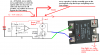
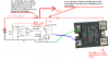
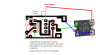
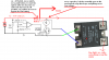
Looks like you missed the power and ground to the nte928m, other wise, it looks fine and with that IRF510, you could drive a pretty hefty relay, but if you do, don't forget the reversed diode. Still think you should consider using IRF4905, IMHO
Do you make your own PC boards?
Here's some relays that may interest you.**broken link removed**
Kinarfi
Now I see what you were doing a few drawing ago, cool, this will work and the system will shut itself down at low voltage and stay shut down until reset or bypassed.
Kinarfi
OKAY!!!so the system works in that it shuts down pretty consistantly at 10.01~V BUT i dont have a relay to test the reset idea... but i see in theroy it works.... so i guess my next step is to get a relay and do a real test, then redraw my board etch it and be good.
Thanks K for all your help
EDIT
i found a relay, but it seems like its just trying to reset its self (when you hit the momantary the relay BUZZES rather than latching and staying latched) ugh i hate electronics sometimes
When you say relay, do you mean mechanical with coil and armature and contacts or an SSR solid state relay? What's your power supply?
Draw an as built schematic, Got any small pieces of aluminum laying around, maybe even some Channel or Square tubing that's relatively thick 1/8" to 1/4"?
I'm still thinking that this could be a nice small package by using the IRF4905 heat sinked to a small piece of aluminum with a circuit board about the same size as before, but reverse the inputs to the nte928m, Want a suggested schematic?
no....ill probably change out the components, but i would like to figure out why it wont hold the relay open? i did tests without the relay (used an LED) and thats how i found it functioned well at 10.02V ...so i guess i should try a different relay???? argghh
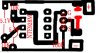
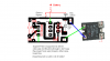
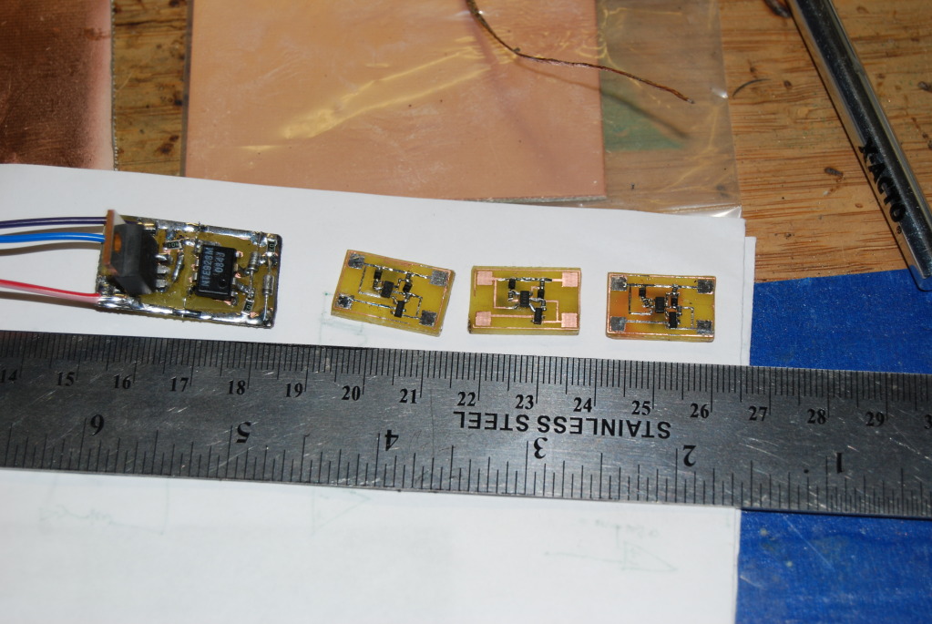
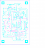
That looks good, do you do your own etchings? I'm thinking I should do some also, it cost me $200 for 10, but lots of holes. How hard are smds to do, looks like you like them.
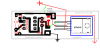
How hard would it be to make 2 sided and convert to smds for a board like this one?
Kinarfi
the SMDs are not great for prduction unless you have the equipment, by hand SMD is tough, but i was going for small, sooo i have no clue how much that would cost, not tomention you could redesign the lay out and possibly find a better solution than 2 sided (i just have a hard time lining up my 2 sided stuff so i always try to get it 1 sided )
by the way i reversed my compareitor resistor and zeners on the above boards...hence why they didnt work, making new ones with the new swithces too.
This site uses cookies to help personalise content, tailor your experience and to keep you logged in if you register.
By continuing to use this site, you are consenting to our use of cookies.

")