Electro Tech is an online community (with over 170,000 members) who enjoy talking about and building electronic circuits, projects and gadgets. To participate you need to register. Registration is free. Click here to register now.
Welcome to our site! Electro Tech is an online community (with over 170,000 members) who enjoy talking about and building electronic circuits, projects and gadgets. To participate you need to register. Registration is free. Click here to register now.
well the problem is when the system is at rest, the stator will not be charging, so if it was to sit for a few days, the draw of the relay would end up draining the battery
not sure I fully understand your set up, if it is like a car, you don't need this because the generator/alternator has diodes that prevent discharge, can you make a block diagram of your set up or further explain what your doing?
Thanks
Kinarfi
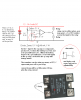
The 5 V was the zener, see drawing. Looked up the specs on the zener and saw no min current, you could probably use 10k load resistors for even lower current drain.
How about a block diagram of what your doing
battery ----- monitor------- stator or generator-----load---what drives the stator?
by the way thank you!!! i like how simple this just got.
ummm these say they are low resistance solid states,7mohm so how long would a 2.3 amphour battery last holding this closed with this circuit? i failed with my v=i*r
by the way thank you!!! i like how simple this just got.
You're welcome
ummm these say they are low resistance solid states,7mohm so how long would a 2.3 amphour battery last holding this closed with this circuit? i failed with my v=i*r
The 7mohms is on the output - the input draw at 12V is probably around 10 ma, a 50 cent LF356N, a 44 cent LM393N or 17 cent LM339, about 2 ma, and using 10K resistors you would have around 2 ma for a total of about 14 ma.
about a weeks worth of continuous on. Flip the op amp/comparator over so it is off and turns on at low voltage and it would run much longer.
Where's my block diagram or description of what your doing?
As you can see, I like simple and I like easy. Tell me what your doing, maybe I can find easier method.
Not necessarily, are you trying to detect a low battery
are you trying start an engine when the battery gets low, If I knew, I might be able to help.
Or is it a secret?
No, no secret, just don't want a battery to go below set voltage... Ie you leave the lights on, you just turn off the lights wait a sec and then you crank it over
mount 2 IRF4905 FETs with insulation to a heat sink or a piece of aluminum and butt splice a #14 or #16 copper wire to each lead of each FET and tie Gate to gate, source to source and drain to drain .
The output of the op amp will be low until the voltage drops below 10.2, then the output goes high and turns the FETs off. Each FET is rated for 72 amps and I doubled them but doubt I need to.
Assuming one heavy wire to the starter and a #12 or #10 to the rest of the vehicle or if Chevy and you have the connection block on the fire wall, cut the wire and tie the battery side to the source and the drain to the other side going to the vehicle. Tie the gates to the output of the op amp. The resistor from source to gate is to turn the FET off when the output from the op amp goes high.
I'm just over the hill if you need help.
leave enough wire to bypass if all fails and throw a wire nut in your glove compartment. Ha ha.
Well, I am going to use the one above with the op amp driving the ssr. I thought we had already got this worked out. Do you think this system is insufficent?
I'm still going to want to use the relay, I want to start it off the circuit. I just wish there was an even more effiecent relay, or a high side design with sufficent terminals for ~40A
Mr. Pita, here's my last suggestion/thought for you to consider. You need something to drop out and lock out if your battery runs down, I suggest a small signal mechanical relay with a button to reset it. For the sake of example, let's say you left your lights on, as the battery pulls down to 10.2 volts, your lights will go out, the battery will start to regenerate and your lights will come back on. With a mechanical relay that holds itself in, once it drops out, it will stay out.
BTW, your 40 amp relay with nice terminal probably cost twice what the fets would have and 2 fets would carry 3 times the current and you probably still need a heat sink.
Best of luck
Kinarfi
this is EXACTLY what i want, so basicly, what is happing, is the circuit is operating up to the 10.2, then the system drops out, and will not turn on until a momentary is touched and resets the system.
thank you Kinarfi!!!!and just for FYI, the fet is like .25 cents and the SSR is $21 but this is what i want to do.
This site uses cookies to help personalise content, tailor your experience and to keep you logged in if you register.
By continuing to use this site, you are consenting to our use of cookies.

")
 here's my last suggestion/thought for you to consider. You need something to drop out and lock out if your battery runs down, I suggest a small signal mechanical relay with a button to reset it. For the sake of example, let's say you left your lights on, as the battery pulls down to 10.2 volts, your lights will go out, the battery will start to regenerate and your lights will come back on. With a mechanical relay that holds itself in, once it drops out, it will stay out.
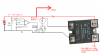
 but this is what i want to do.
 EDIT: Nevermind... i see you have it open at the cap now