Continue to Site

Welcome to our site!

Electro Tech is an online community (with over 170,000 members) who enjoy talking about and building electronic circuits, projects and gadgets. To participate you need to register. Registration is free. Click here to register now.

  • Welcome to our site! Electro Tech is an online community (with over 170,000 members) who enjoy talking about and building electronic circuits, projects and gadgets. To participate you need to register. Registration is free. Click here to register now.

how? momentary switch light up leds in order?

Status
Not open for further replies.

Neilyboy

New Member
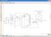
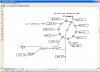
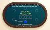
I have a friend who is building a poker table. His idea is to have an led in front of each seat at the table. The light will indicate the 'dealer'. So what he was wanting was a button (I was thinking a momentary switch) under the table by the dealer. He is wanting the light to move around the table as the play progresses. So when he presses the button the light that is lit will go out and the next light around the table will light and so on.. so it would look like

* - - - -
press button
- * - - -
press button
- - * - -
press button
- - - * -
press button
- - - - *


you get the idea. I am fairly fresh when it comes to electronics but understand them. I just need to know is there some sort of a chip which will do this for me. I have a feeling there has to be something simple out there for this type of application I just do not know what it would be.

Thanks for any help you can provide me!

Neil
 
CD4017 Johnson Counter. 10 outputs (though can be less). Each clock (pushbutton) input moves the "high" output in the manner of your diagram.

The 4017B Decade Counter

Ken
 
Last edited:
Actually, that isn't the exact circuit you need. That one continuously moves the "dot". It was just a visual example of the 4017. You only need the CD4017BE. How many player positions are required? Will this # vary? Do the LED's need to be particularly bright?

I can do up a schematic later, unless someone here beats me to it.

Ken
 
Well it would probably be 10 positions if possible.
A schematic would be awesome as I am a visual learner

led's would need to be somewhat bright if I can get them 3v that would be ideal.

neil
 
Last edited:
Here is a better description

as well as more examples
perhaps a rotary switch to determine how many players.
count to N and recycle.
I have several circuits, just need to find
 
One problem =2 many players

Poker is usually played with up to 6 players only due to the fact that there are 52 cards in a deck and playing 7 card stud with only one deck would be pretty hard.
I was contemplating this circuit last night where the dealer inputs # of players then the leds light up as play progresses. If you have a count to N circuit you need to change N according to # of players.
My thought is 2 BCD counters - one for input of # of players, second counter to compare with first then reset to one. A 4017 or 74154 ic to run the leds in sequence.
fairly basic circuit. no need to complicate with pic.
thoughts on ic's = 74196 counters (one to store # of players and one to count. A couple of and gates to compare BCD outputs, a contitioning circuit for the monentary push button, and a 74154 or 4017.
cmos ic's would be ic of choice..
 
Alright you are going a little deeper than we need it to be haha. It just needs to be a simple circuit where when a button is pressed the light moves to the next light in sequence. It is ok if the light lights up on a seat that is not taken since there may be a game of 5 and may be a game of 10 with people sitting wherever around the table. The dealer will just hit the button until the light is on the next seat which is taken. He is building a texas hold'em table so each player only gets two cards (which is why more people can play). So all I need is a basic circuit which will move a light from position 1 to position 2 then from 2 to 3 and so on. No need to input number of players for this particular application. Any help with a simple circuit like that?

Thanks again for all of the help so far.

Neil
 
I think this will do it. This has not been bench tested, so you may have play with the C1/C2 capacitors for the switch debounce.The output to the LED's is ~13mA. For a little brighter replace the 330Ω resistor with a 220Ω one, for 20mA. This counter could be done with a CD4071, but would require some kind of driver between the CD4017 and the LEDs.

Ken
 

Attachments

  • Poker74HC4017.gif
    Poker74HC4017.gif
    21.2 KB · Views: 481
remember im a newb so when you say driver haha.. im googling it now but im still learning.

neil

The CD4017 has a wider supply voltage range, but can only supply <1mA to the LEDs. Not very bright. You would need a buffer between the counter and the LED's to amplify the current. The 74HC4017 can supply the LEDs directly.

I forgot to add that the 74HC4017 has a max power supply voltage limit of 7VDC, so your power supply must be regulated at 5V or 6VDC.

Ken
 
Last edited:
This might be the trick??

I forgot to add that the 74HC4017 has a max power supply voltage limit of 7VDC, so your power supply must be regulated at 5V or 6VDC.


The 4017 can run on 3-15V+
Here is a non tested circuit that uses a 10 position rotary that can be had for under $4
The second pic shows how the rotary switch is connected to the 4017
have an alternative method but not sure if the circuit will still count to N and recycle.
It should but 1 resistor might work?? as shown
It would get confusing if you have leds light up bu no player. ?? who's turn??
 

Attachments

  • Capture2-9-2009-7.29.31 AM2-12-2009-5.42.27 PM.jpg
    Capture2-9-2009-7.29.31 AM2-12-2009-5.42.27 PM.jpg
    122.5 KB · Views: 238
  • Capture2-9-2009-7.29.31 AM2-12-2009-5.42.40 PM.jpg
    Capture2-9-2009-7.29.31 AM2-12-2009-5.42.40 PM.jpg
    125 KB · Views: 201
hahaha ok.. I do appreciate the help man as I would be nowhere without it. I am sure you understand it but the circut does not need to be overly complicated. If I can have a button press move the light one place every press thats all I need.

thanks again for all the work I appreciate it.
 

Attachments

  • holdem.jpg
    holdem.jpg
    70.4 KB · Views: 216
could just a rotary switch work?!?! If its just that simple... Can I just throw 3v to a switch and wire each position on the switch to an led?

Neil
 
Yes but the rotary switch

would get a heck of a work out.
The circuit I posted should work and cost under $20
maybe even $15
A pc board would be nice. mount the rotary switch on one side and circuit on other
about 1 hours work including etching a board.
 
MrBED,
About your circuit:
1. With a 270Ω LED-resistors and a 9V supply you are going to pull 27mA from the outputs...that are only rated at ~3.5mA on a CD4017.
2. And I've seen this in several versions, since only one LED will be ON at a time, you only need one LED current limiting resistor. Tie all the LED cathodes together and to one resistor, that goes to ground.
Ken
.
 
oups supposed to be 470

I think one resistor might work but with the rotary switch I think it adds a problem
I followed this circuit
look at last circuit in particular. why reinvent the wheel?
basically same circuit but added rotary switch.
I still like the idea of inputting # of players with 7 segment display.
I wonder if there is a market for this ??
also 10 players seems a bit too many.
 
10 to many? you ever watched the world series of poker on tv? The LED in our scenario is taking the place of the 'dealer button'

**broken link removed**

check out some of the photos there on the site.. They play tournaments with 10 all the time. What would be the problem with just throwing together a 10 pos rotary switch to a resistor to each led?

thanks again for all the help guys.

neil
 
Status
Not open for further replies.

Latest threads

New Articles From Microcontroller Tips

Back
Top