Continue to Site

Welcome to our site!

Electro Tech is an online community (with over 170,000 members) who enjoy talking about and building electronic circuits, projects and gadgets. To participate you need to register. Registration is free. Click here to register now.

  • Welcome to our site! Electro Tech is an online community (with over 170,000 members) who enjoy talking about and building electronic circuits, projects and gadgets. To participate you need to register. Registration is free. Click here to register now.

How is this guy detecting color with cny70?

Tigger1

New Member
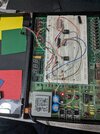
I've built this in my breadboard and it doesn't work the same as the video shows. It is much less sensitive. The voltage given by the first potentiomete to pin 5 by any colour (red green yellow) is about 4.7v and one led to the right, however whenever i put black on the sensor it drops to 1.1v and no led turns on. Showing it a dark brown gives about 1.9v and it opens a led on the left.

I read that there was no way a cny70 could detect colors in a post from here on 2004.


Any help is greatly appreciated. I've already brought this problem to reddit and we came to the conclusion that there was a problem with the sensor circuit but it is exactly the same as androbot, except that i have a cny70 tfk 136 and he had a tfk 102.
 

Attachments

  • Schematic_sensor color cny70 y 3914_2022-03-31.pdf
    48.1 KB · Views: 252
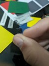
  • PXL_20231224_172549717.MP.jpg
    PXL_20231224_172549717.MP.jpg
    7.1 MB · Views: 223
  • PXL_20231225_164301934.MP.jpg
    PXL_20231225_164301934.MP.jpg
    6.7 MB · Views: 203
The CNY70 is for infra-red. It emits with a 950nm wavelength and includes a daylight-blocking filter. Methinks the video is a scam (like so many on U tube).
 
Exactly, my teacher gave me this video as an assignment and now I've got a shades detector. This build is really important for my final grade but I don't know how to continue. If you could, watch the video and tell me if you got any ideas of how he's doing it.
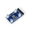
You'd better use TCS3200 color sensor if your teacher allows it.
 

Attachments

  • 1703607176065.jpeg
    1703607176065.jpeg
    3.8 KB · Views: 189
He has it set up so it’s a constant height above each coloured sheet, so should give a repeatable output.

Adjust the sensitivity so each colour gives a different level, then put the coloured LEDs In the positions that match.

Use plain uncoated papers, or whatever materials give distinctly different outputs.
I have a constant height at about 7 mm. Could more distance be better?

That's the problem, each colour does not give a different level no matter the value of the first potentiometer.

Printed paper doesn't work. Cardboard and reflective paper work fine but i don't have many shades of the same color and, sadly, different colors of the same shade don't change.
 
Some black paint looks white under IR. It all depends on the paper on how much IR it deflects. Ink will be glossy, these are all matte papers. If you have laser colour + black carbon printer, that might work on printed paper but not ink-jet. The video uses special paper.. Better to use transparent colour film as a lens on the detector with a white LED. They make white sensors that filter the IR detector to shape it as the eye sees it (Vishay light sensor)

But your problem is in the reflective ink. The only black source that worked for me was a Sharpie pen. We used to put a strip on the aluminum disk for a power meter and made into a smart IR power meter reader with a 928 MHz ISM radio.
 
I'm not sure if this could help or just spark some ideas.

In the Radio Electronics magazine, much more than 10 years ago, they published a project in which a flat card painted with a certain color was illuminated in sequence by 3 (or 4?) different LEDs. The reflected light of each LED was quantified (ADC conversion) and recorded. The group of 3 (or 4?) measurements was assigned a name.

Next time, if another card with the same color was tested following the same procedure, the 3 (or 4?) values would eventually match allowing the current card's color to be identified after comparing values.

Repeatability? I have no idea. I tried to contact the authors (from some university in Canada) but they did not reply. I lost my enthusiasm and now it's just a vague recollection.
 
Last edited:

Latest threads

New Articles From Microcontroller Tips

Back
Top