Electro Tech is an online community (with over 170,000 members) who enjoy talking about and building electronic circuits, projects and gadgets. To participate you need to register. Registration is free. Click here to register now.
Welcome to our site! Electro Tech is an online community (with over 170,000 members) who enjoy talking about and building electronic circuits, projects and gadgets. To participate you need to register. Registration is free. Click here to register now.
For an AC power line current transformer, the primary is generally just 1-turn, consisting of one phase of the power line going through the hole in a toroidal magnetic core. The secondary is wound on the core with the number of turns to give the desired ratio of power line current to output current. For example if you want 1A output with 100A line current, the secondary would have approximately 100 turns (give or take a few for tolerances).
The magnetic core is sized so that it will give a linear output up to the desired maximum current and compliance voltage. (The compliance voltage is the maximum output voltage that can be generated in the secondary output external resistive load while still maintaining accuracy.)
Of course the turns ratio has meaning. The voltage on a winding is the flux through the winding times the number of turns. Since windings wound on the same core, share the same flux, then their relative voltage is equal to the turns ratio.
I believe the problem is semantics. All transformers are wound on the same core even if the winding are distributed on a different part of the core. How would you wind a transformer without the windings being on the same core?
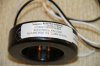
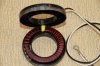
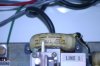
Let's see if a picture is worth a thousand words. The first image is a 200:5 current transformer. Looks a little like a donut with a hole through the center. The primary current carrying conductor passes through the center. The last image is of the configuration. Not the same current transformer but note the primary conductor passing through the center. The second image shows two leads exiting the transformer and those are the secondary winding.
So what is in there? Well lets open it up and take a look. Image three shows the innards of the CT. We see a round iron core wrapped with wire. Since the secondary must carry 5 amps and the wire gauge is small in this case it is parallel wires wrapped around the core. However, I am sure you get the idea.
This is about "Amp Turns" on the primary and a single conductor passed through the primary is one amp turn. OK if we have in this case with this transformer 200 amps and a single conductor (note it has a large hole for large gauge wire) the output will be 5 amps on the secondary. We won't get into "Burden Voltage" at this point. If I were to loop that primary conductor through the coil again then 100 amps would equal 5 amps out and thus it continues.
To emphasize what crutschow stated, even if I loop multiple turns through the hole, it is still the same core as can be seen in the images.
I got you know.
So actually the CT - as it comes out of the factory - contains only a Seconday Winding which is wound on its magnetic core, right?
And the Primary Winding is considered to be the Current Carrying Wire (such as, Live wire of an household), right?
I got you know.
So actually the CT - as it comes out of the factory - contains only a Seconday Winding which is wound on its magnetic core, right?
And the Primary Winding is considered to be the Current Carrying Wire (such as, Live wire of an household), right?
That is pretty much the case. There are few exceptions but when you hear the term current transformer it is pretty much about what I posted images of. The primary is the conductor carrying the current to be measured and only a secondary is wound on the core. The primary current carrying conductor can be looped through the hole increasing the amp turns.
If you ever plan to employ the use of a CT there are important considerations for what is called "Burden Voltage" as well as other factors to consider. Current transformers can also come with a split core making them easier to install. You always want a load on the secondary and never disconnect the secondary while a CT is in use.
HI there Ron, I ws searching through the internet to find some visual information to explain the construction of CT's to which I came across this old post.
My question in terms of these pictures is when you count up the turns, you get approx 40 turns of two conductors / wires for each turn, therefore is this the 200/5A CT, which I am expecting to be approx 40 turns of conductor. Therefore I am assuming that the these two parrallel conductors would be connected to one secondary wire leaving the CT (say via the black wire) and the other two ends of the turns of wires connected to the white wire. If this is in fact the case, why do they do this and is a common practice.
It is fairly common to put windings in parallel. There are various reasons for doing it. In this case, It looks as though they have done it to keep the transformer as thin as possible.
For high frequency applications it is done to reduce the skin effect.
Great CT photo's.
It is easier to wind the thinner gauge of wire as well and as already mentioned.
Sometimes on multitap CT's e.g. 150 / 250 / 400 / 5 Amps the lower 150 / 5 amp tap has the normal gauge wire and often a thinner compensating winding in parrallel with it.
Metering CT's are also earthed at one end for safety reasons.
For metering applications a test block is fitted with shorting links for the CT's so that a CT meter can be changed without a power shutdown.
You got it. The transformer is a 200:5 making it a 40:1 ratio. It should be noted there may not be an exact ratio of turns primary to secondary as the secondary turns must account for leakage and other factors in real life. The turns are in fact two conductors in parallel. This method allows the use of smaller gauge wire but for it to work well the secondary windings must share the load equally. I am not sure how common the practice actually is. I have seen it used quite a bit. This practice may also be used for impedance matching but I am unsure.
This site uses cookies to help personalise content, tailor your experience and to keep you logged in if you register.
By continuing to use this site, you are consenting to our use of cookies.