Electro Tech is an online community (with over 170,000 members) who enjoy talking about and building electronic circuits, projects and gadgets. To participate you need to register. Registration is free. Click here to register now.
Welcome to our site! Electro Tech is an online community (with over 170,000 members) who enjoy talking about and building electronic circuits, projects and gadgets. To participate you need to register. Registration is free. Click here to register now.
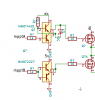
No it doesn't. If you input a square wave of 0 - 3.3 volts at point mpptB, you can expect an output at pins 1,4 of 0.6V - 2.7V. Now 2.7 volts may be enough to turn the MOSFET on fully, depends on the MOSFET.
It's now made sense why bucks offering 100% duty cycle (aka bypass) can't use bootstrapping so use a PFET on the upper.
I used the above circuit plus a similar one to drive the top. [dc] is limited to 16v. Both drivers are 600mA rated which should be plenty for the small fet's I intend to use.
dc=16V? -> yes, no more to protect the gate. May lower a bit.
Will the bottom MOFET turn on well at 4V on the gate? -> Yes, they lower dc helps to get fast low Vgs fets. Won't be 4 though, more like 2.5v!
What is the voltage of mpptB? 5V? -> 3.3v (the 2.5v is a bit of a worry but it'll still be "mostly on" and there's a schkotty just out of shot parallel to the fet)
Bottom MOSFET pin1 at gnd? -> correct
A number if companies make "gate drivers". This one needs a supply in the 5 to 30V range. (you have 16V)
You can choose inverting or not-inverting or one of each.
Input signal is "ttl levels" and the output is ground to Vcc.
Just a thought. RonS.
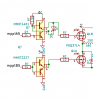
I've made another mistake, the PFET is swinging to ground.
I think a better solution would be to keep it as NFET and drive it with a higher voltage of say 15v. I know when directly connected to the load this would give a healthy 10Vgs but what about when there's an inductor in the path?
This site uses cookies to help personalise content, tailor your experience and to keep you logged in if you register.
By continuing to use this site, you are consenting to our use of cookies.