Continue to Site

Welcome to our site!

Electro Tech is an online community (with over 170,000 members) who enjoy talking about and building electronic circuits, projects and gadgets. To participate you need to register. Registration is free. Click here to register now.

  • Welcome to our site! Electro Tech is an online community (with over 170,000 members) who enjoy talking about and building electronic circuits, projects and gadgets. To participate you need to register. Registration is free. Click here to register now.

How does this circuit work

Status
Not open for further replies.

neptune

Member
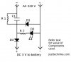
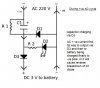
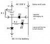
(D1 and D3 are diodes IN4007 and D2 is LED, R1=56 gigs ohms and R2 is 220 Mega ohms)
ok this person has built a battery charger without using step down transformer
How are we getting 3 V output ?
when +ve half cycle goes D1 stars conducting the capacitor charges normally but when -ve cycle goes , from where does the capacitor discharges through R1 or it goes directly to D3, what is the current direction ?
 

Attachments

  • battery-charger-circuit-diagram.jpg
    battery-charger-circuit-diagram.jpg
    25.2 KB · Views: 303
Bad, and dangerous circuit. It is the value of C1 that determines the current supplied. Circuit acts as a current source so there is no charge voltage cutoff on the battery.

The resistor across C1 is just a high value bleeder resistor to discharge the capacitor with circuit is unplugged.
 
Last edited:
There is a schematic error. D2 is backwards and will most likey be damaged by reverse voltage breakdown if installed backwards. This is a hokey amateur circuit that does not consider high frequency or rapid interference pulses that may occur on the incoming AC voltage (and hence getting through the series capacitor).
 
Last edited:
how come 220V is being step down to 3V !
so will this circuit work or not, if not why so ? whats the correct scheamatics
 
The circuit might work. It depends on what it is connected to.

D2 is the wrong way round in the diagram. It is the light that shows if there is an output voltage. However the light will flicker at 50 Hz.

The capacitor will limit the current drawn from the 220 V supply. Only AC current can pass though a capacitor, so there has to be as much forward current as reverse current. The forward current will go though D3, to the load. The reverse current will go though D1.

The circuit has three major problems as drawn, and two minor ones.

The largest problem is that there is no isolation from the mains input, so every point on the circuit has to be considered to be at mains voltage. There is nothing that you can do about that with this kind of circuit.

One major problem is that there is nothing to limit the output voltage. The current is limited by the capacitor, but with no load there will be hundreds of volts on the output. A zener diode or something similar should be added across the output to limit the voltage if there is no load.

The second major problem is that the capacitor will take a huge current if the circuit is turned on near the peak of the mains cycle. You should add a 1k resistor in series with the supply to limit the turn-on surge.

The first minor problem is that there is no smoothing of the output. The output voltage will be nearly zero for half of each cycle. You could add an electrolytic capacitor to smooth that out.

The second minor problem is that the LED is the wrong way round. In fact, if you have a capacitor, and you put the LED and resistor across that, the LED won't flicker.

However, it is usually far easier to find an old cellphone charger to do what that circuit does. That has none of the problems of this circuit.
 
Charging current is half sinewave current pulses.

The reactance of C1 is the voltage dropping element. Think of it as a series resistor that limits current.

C1 = (Ichg + Iled) / (0.45 x 2 x pi x Fmains x Vrms). The 0.45 is factor for average current from a half wave rectified current pulse.
For battery charging unfiltered current is okay as long as you take into account averaging factor. You may see 50Hz flicker in LED.

Again, D2 polarity is correct as shown in diagram. LED does need to be reversed.

Without mains isolation, this circuit is dangerous. I would not use it for a charger. Many commercial LED lights use similar capacitor ballast circuit but usually with full wave rectifier.
 
how can capacitor both charges and discharges via D1 ?

It charges through D3 and discharges through D1. It works identically to a voltage doubler circuit, in terms of charging paths.
 
Last edited:
The circuit might work. It depends on what it is connected to.
.
what do you mean ?
The second major problem is that the capacitor will take a huge current if the circuit is turned on near the peak of the mains cycle. You should add a 1k resistor in series with the supply to limit the turn-on surge.
wouldnt there be a huge current surge when the capacitor will discharge during -ve cycle of AC ?


One major problem is that there is nothing to limit the output voltage. The current is limited by the capacitor, but with no load there will be hundreds of volts on the output. A zener diode or something similar should be added across the output to limit the voltage if there is no load.
so it is not stepping down the voltage at no load as it is supposed to do !
 
Last edited:
It charges through D3 and discharges through D1. It works identically to a voltage doubler circuit, in terms of charging paths.

here what i found about what would happen to current during both -ve and +ve half cycles .. but i find it really absurd
 

Attachments

  • 1.jpg
    1.jpg
    62.2 KB · Views: 150
  • 2.jpg
    2.jpg
    47.9 KB · Views: 177
Last edited:
Forget about R1 for a moment. Pretend it has been removed from the circuit. When current flows counter-clockwise in the circuit, it flows through C1, D3, external circuit ( battery in this case ) then through the -ve leg. During the other half-cycle, current flows through the -ve leg, D1 and C1. Thus the cap charges through D3 and discharges through D1.
 
D2 polarity is correct as shown in diagram
I don't think so. When D1 is forward biassed it 'shorts out' the LED + R2 string. So the LED won't light on either half cycle.
This is a potentially lethal circuit for a charger, if users are able to plug/unplug batteries without bothering to turn off the mains supply.
 
Originally Posted by Diver300
The circuit might work. It depends on what it is connected to.
.
what do you mean ?
If the load can absorb current all the time, then the output voltage will not get too large. Also if the supply has some resistance, the surge current will not be too big.

If those conditions are met, the circuit will work OK.

Originally Posted by Diver300
The second major problem is that the capacitor will take a huge current if the circuit is turned on near the peak of the mains cycle. You should add a 1k resistor in series with the supply to limit the turn-on surge.
wouldnt there be a huge current surge when the capacitor will discharge during -ve cycle of AC ?
No. Mains is basically a sinewave, so the rate of change of voltage is well defined. The instantaneous current though a capacitor is the capacitance times the rate of change of voltage. At the point where you turn on, the rate of change of voltage could be huge, resulting in a huge current. When running, the rate of change, positive or negative, is small, so the current is small.


Originally Posted by Diver300
One major problem is that there is nothing to limit the output voltage. The current is limited by the capacitor, but with no load there will be hundreds of volts on the output. A zener diode or something similar should be added across the output to limit the voltage if there is no load.
so it is not stepping down the voltage at no load as it is supposed to do !
No. Without a shunt regulator, that circuit won't work.
 
ok driver300 thanx for making it clear
 
Forget about R1 for a moment. Pretend it has been removed from the circuit. When current flows counter-clockwise in the circuit, it flows through C1, D3, external circuit ( battery in this case ) then through the -ve leg. During the other half-cycle, current flows through the -ve leg, D1 and C1. Thus the cap charges through D3 and discharges through D1.
understood, but during other half cycle current can also flows through -ve leg, D1,D3 to +ve leg also instead of -ve leg, D1 and C1.
also correct me that how can capacitor will discharge through D1 when it is reverse biased in respect to capacitor ? i think it will dicharge through D3 on other half cycle , when current is flowing clock wise.
 
understood, but during other half cycle current can also flows through -ve leg, D1,D3 to +ve leg also instead of -ve leg, D1 and C1.

Current can only flow from a higher voltage to a lower one. If it flows as you say, then it flows through -ve, D1, D3, battery, then where? Back through -ve again???? That would be quite impossible.


also correct me that how can capacitor will discharge through D1 when it is reverse biased in respect to capacitor ? i think it will dicharge through D3 on other half cycle , when current is flowing clock wise.

D1 is forward biased in the 2nd half-cycle. C1 was charged to +ve in the first half cycle. So, it's voltage is in series-aiding in the 2nd half cycle.
 
Hi,

I agree, this is a dangerous circuit. Why? Because there is no surge limiting resistor
in series with the cap. When a circuit like this is designed properly, there is always
a surge limiting resistor in series with the cap. The surge limiting resistor limits
the current through the cap during turn on (or plug in). Without that resistor the
current is limited only by the small series ESR of the cap and that's not considered
good enough in most cases. What this means is that the battery could see a huge
current surge and even if it doesnt last very long (it doesnt) it's still not safe
because the terminal voltage could rise pretty high and cause an explosion.

The above is definitely the first thing to consider, and second to that the LED labeled
"D2" is shown connected backwards. It can never light up because the diode D1 shorts
out the line when the right side is positive and left side negative, so the most
'forward' voltage D2 will ever see is about 0.7 volts, which is not enough even for
a red LED. Turn the LED around though and it works.

This class of circuit is called an "offline" power supply because it works directly
off the power line without a transformer. The capacitor voltage is out of phase
with the line and so subtracts most of the voltage from the line so we end up left
with a small difference which can light up D2 if D2 is connected properly, and also
charge the battery a little bit.

So the first thing to do is add a current limiting resistor, and the second thing
to do is to reverse D2. The current limiting resistor has to limit the surge to
some safe level and also has to be able to stand the power dissipation when the
circuit is operating full time. Sometimes a quarter watt resistor works but other
times a larger size like 1/2 watt or even 1 or 2 watts has to be used. It depends
on the current demand of the external circuit (like the battery).

Offline power supplies are used quite a bit these days, but yes there is also the
danger of electric shock due to the fact that the battery will not be isolated from
the dangerous line voltage. That's something to keep in mind and provide some
sort of protection for.


If you tell us the current requirement we could suggest all the component values
for this circuit.
 
Last edited:
Status
Not open for further replies.

Latest threads

Back
Top