Continue to Site

Welcome to our site!

Electro Tech is an online community (with over 170,000 members) who enjoy talking about and building electronic circuits, projects and gadgets. To participate you need to register. Registration is free. Click here to register now.

  • Welcome to our site! Electro Tech is an online community (with over 170,000 members) who enjoy talking about and building electronic circuits, projects and gadgets. To participate you need to register. Registration is free. Click here to register now.

How does this circuit work

Status
Not open for further replies.
during first half cycle when current is flowing anti clock wise , through capacitor, D3 and battery but wouldnt it flow through D1 and cause breakdown of that diode. 220v connected in parallel to Diode IN4007.
where is voltage stepping down in this circuit ?

.D1 is forward biased in the 2nd half-cycle. C1 was charged to +ve in the first half cycle. So, it's voltage is in series-aiding in the 2nd half cycle.
how capacitor is aiding in 2nd cycle, during 2nd cycle current will come from opposite side through D1 and to (-ve side) of capacitor, and capacitor which was previously charged starts discharging in opposite direction like back to the mains supply. so there will be current addition of capacitor and AC supply current coming from D1. wouldnt that cause problem ?
this circuit will act as half wave rectifier
 
Last edited:
during first half cycle when current is flowing anti clock wise , through capacitor, D3 and battery but wouldnt it flow through D1 and cause breakdown of that diode. 220v connected in parallel to Diode IN4007.
where is voltage stepping down in this circuit ?


C1 provides a voltage drop in accordance with the equation xC=1/2*pi*C. It drops the voltage from the line voltage value to ~+3.7V. D1 can easily handle that reverse voltage.

how capacitor is aiding in 2nd cycle, during 2nd cycle current will come from opposite side through D1 and to (-ve side) of capacitor, and capacitor which was previously charged starts discharging in opposite direction like back to the mains supply. so there will be current addition of capacitor and AC supply current coming from D1.

Capacitor C1 is charged to "+" on the top place ( as shown ) during the counter clockwise current cycle. During the next half cycle, the polarity of C1 aids the current flow from the AC mains.

wouldnt that cause problem ?

The current from the capacitor would be very small in comparison to what the mains can safely handle. So no problem.
 
Last edited:
C1 provides a voltage drop in accordance with the equation xC=1/2*pi*C. It drops the voltage from the line voltage value to ~+3.7V. D1 can easily handle that reverse voltage.
So if capacitor is stepping down well and we provide sereis resistor to stop the sudden current surge and reverse the LED, the circuit will work fine, but circuit is dangerous when no load is connected to or when battery is fully charged, because at that time voltage at output starts increasing , .therefore we need to provide shunt regulator ! But why would voltage at output start increasing by itself?
 
Last edited:
Hi,

The output voltage should not increase just because the battery is charged, unless it disconnects itself from the circuit.
The output voltage will also not increase if the value of R2 is low enough to cause significant conduction in D2, and D2 can take the extra current.
If the battery is wired in permanently this might not be a problem unless the battery becomes defective.

The real problem i think is that most people assume batteries have low voltage and cant hurt them, yet with this circuit if they grab the negative or positive lead of the battery and a water faucet they could be dead unless the negative lead is connected to ground and that's not always the case even when we take care to try to get it that way. That's why these kinds of power supplies are used when there's no chance of the user touching any node in the circuit. You'll find these circuits in quite a few products, but if there's a chance someone could touch part of the live circuit then you probably wont find this kind of circuit in that product, but rather a circuit with a specially wound transformer that actually has the primary and secondary physically separated from each other on the transformers metal core either on separate bobbins or a dual bobbin with a separator to keep them apart.

With the use of wall warts so common these days it's more popular to design battery chargers that run off of them so there's very little danger of electric shock. Unless this circuit will be wired into a permanent installation enclosed in a case you really should consider using a wall wart instead.

The circuit itself can be more easily understood by considering the bottom of the capacitor in the schematic to be an AC signal, and the capacitor voltage is also AC and almost the same voltage level as the incoming line voltage. The cap having almost the same voltage and at reverse phase from the line, the AC voltage remaining is the voltage that runs everything. So it's like having a low voltage source at the bottom of the cap, provided of course that everything is working right. The capacitor provides energy storage so the efficiency is much better than using a resistor to drop the extra voltage.
 
Last edited:
Hi,

The output voltage should not increase just because the battery is charged, unless it disconnects itself from the circuit.
The output voltage will also not increase if the value of R2 is low enough to cause significant conduction in D2, and D2 can take the extra current.
If the battery is wired in permanently this might not be a problem unless the battery becomes defective.

so if battery becomes fully charged , it would be same situation as no battery connected , then wouldnt circuit become dangerous ?

The real problem i think is that most people assume batteries have low voltage and cant hurt them, yet with this circuit if they grab the negative or positive lead of the battery and a water faucet they could be dead unless the negative lead is connected to ground and that's not always the case even when we take care to try to get it that way. That's why these kinds of power supplies are used when there's no chance of the user touching any node in the circuit. You'll find these circuits in quite a few products, but if there's a chance someone could touch part of the live circuit then you probably wont find this kind of circuit in that product, but rather a circuit with a specially wound transformer that actually has the primary and secondary physically separated from each other on the transformers metal core either on separate bobbins or a dual bobbin with a separator to keep them apart.
oh i didnt knew that !
so the problem of electrical shock is with -ve terminal only and not with positive terminal ? because it is direct ! and voltage increase is in -ve terminal only.
The circuit itself can be more easily understood by considering the bottom of the capacitor in the schematic to be an AC signal, and the capacitor voltage is also AC and almost the same voltage level as the incoming line voltage. The cap having almost the same voltage and at reverse phase from the line, the AC voltage remaining is the voltage that runs everything. So it's like having a low voltage source at the bottom of the cap, provided of course that everything is working right. The capacitor provides energy storage so the efficiency is much better than using a resistor to drop the extra voltage.
how can cap considered as voltage source when it is discharging in opposite direction, back into the mains supply ! it drops voltage because of its reactance and is out of phase with freq. of main supply .
 
Last edited:
so if battery becomes fully charged , it would be same situation as no battery connected , then wouldnt circuit become dangerous ?
.
I dont see why you would think that a fully charged battery becomes an open circuit. A discharged battery might be 2 volts, a fully charged battery 3 volts, both are low impedance. An open circuit (battery disconnected) is a very high impedance. That's a big difference.

.
oh i didnt knew that !
so the problem of electrical shock is with -ve terminal only and not with positive terminal ? because it is direct ! and voltage increase is in -ve terminal only.
.
Actually the risk of shock is with either terminal. One terminal is only 3v away from the other, so if one terminal is 200v the other is either 197v or 203v, either of which is still dangerous.

.
how can cap considered as voltage source when it is discharging in opposite direction, back into the mains supply ! it drops voltage because of its reactance and is out of phase with freq. of main supply .
"Reactance" is not resistance, the cap stores energy which means at some point the cap puts energy back into the circuit making it look like a source. But that's not the point anyway, the point is that when we consider the bottom of the cap to be a voltage source it's just a simplification to make it easier to understand the circuit without going into detail about how the cap phase and voltage subtract from the mains supply. It's like a sort of AC battery, and two batteries in series is still a source.
Thinking about it this way allows us to look at the rest of the circuit as if it was driven from a low voltage AC source like 4vac. The only difference is that there is still the potential of that 220vac that can cause conduction through an external ground which is a shock hazard risk.

People have actually been killed by audio amplifiers that had one side connected to 'ground' because of faulty electrical outlets or improper use of three lead adapters. The wrong side of the line got connected to ground and when their lips or hand touched the metal of the microphone they were actually killed due to the path from the mic through their body to ground. The designers of the audio amps assumed that the electrical circuit used to power the amps would be connected properly, but all too often it's not. I myself have been shocked in this manner too while performing outdoors for block parties long time ago with one of my old bands. I was lucky though it was just a shock. Reversing the plug in the outlet solves the problem temporarily but that's not a good thing to have to worry about.

Wall warts are almost always made with those special transformers so if you start with a wall wart you will end up with a much safer circuit. Wall warts are cheap these days so do yourself and anyone else who gets ahold of this circuit a favor :)
 
Last edited:
ok thanx,
how do i thumbs up the people who answered in my threads
 
Hi,

You click on the little star under their screen name and that adds to their 'reputation'.

Hey if you can get back here at some point to let us know how you made out with this project that would be nice too, and with some pics would be extra nice.
 
Again, D2 polarity is correct as shown in diagram. LED does need to be reversed.

These two sentences seem to be contradictory. It looks to me like D2 is an LED, so if "...D2 polarity is correct...", then why would it be true that "LED does need to be reversed."?

The LED is lit by its forward current. As the circuit is drawn, the series combination of R2 and D2 see a forward voltage equal to the forward voltage across D1; that will be about .7 volts, which is not enough to light an LED.

When a battery is not connected, then as the circuit is drawn the LED will see a reverse voltage of 220*1.414 = 311 volts applied through R2. Even though R2 will limit this reverse current, it may be enough to damage the LED.

In the circuit as shown, if D2 is reversed from what is shown, then the reverse voltage it sees will be equal to the forward voltage across D1 which will be safe. The forward current it will see will be equal to the reverse voltage across D1 divided by R2. That voltage will be very different when no battery is connected than it will be with a battery in place. If R2 is chosen to provide a reasonable brightness in the LED when a battery is connected, then without a battery connected the LED current would probably be large enough to cause damage to R2 and the LED. As Diver300 suggested, some device such a zener diode should be placed across the battery terminals to limit the voltage there when the battery is not connected. This will provide a modicum of safety by preventing the voltage across the battery terminals from rising to a dangerous level when the battery is disconnected, and will allow R2 to be selected without danger of burning up when no battery is connected.
 
The second major problem is that the capacitor will take a huge current if the circuit is turned on near the peak of the mains cycle. You should add a 1k resistor in series with the supply to limit the turn-on surge.

Let's do a quick calculation. This circuit consists of a capacitor connected in series with a diode arrangement and a battery and then connected to 220 VAC (presumably @ 50 Hz in New Delhi). The diodes and battery part of the circuit will drop a few volts; let's say 3 volts. So what we have essentially is a capacitor connected to 220-3 = 217 volts. Now let's add a 1k resistor in series with that. Let the capacitor be 10 µF, which would be typical for a charger like this; it would give us something like 1 amp charging current. Now we have 1k in series with the reactance of the capacitor which is 1/(2*Pi*50*10E-6) = 318.3 ohms. The total impedance will be 1000 - j318.3; divide 217 VAC by that value and we get a current in the capacitor and in the 1k resistor of .2068 amps. The dissipation in the 1k resistor will be (.2068)^2*1000 = 42.76 watts. This would not be a good choice for the series current limiting resistance.

The worst case initial surge current which would occur if the circuit were suddenly connected to the grid when the grid sine wave is at its peak won't be a problem. The surge will be very short and will be limited by the leakage inductance of the distribution transformer on the pole outside your house. I'm in the U.S. where the voltage at the plug in the house is 120 VAC @ 60 Hz rather than the 220 VAC @ 50Hz in India. But the surge should be similar.

Just to get a feel for what could be expected I performed an experiment. I connected a short line cord in series with a 50 µF 370 VAC rated motor run capacitor with a measured ESR of 18 milliohms, and also in series with a 1 milliohm current shunt. Using an oscilloscope with isolated inputs, I monitored the voltage across the capacitor (which is essentially the grid voltage minus the few millivolts across the shunt), and the voltage across the shunt. The shunt voltage is 1 millivolt per amp. I then repeatedly plugged this arrangement into an outlet (discharging the capacitor before each insertion) until I caught the grid voltage at a peak when I plugged it in.

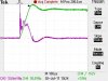
The first image shows the grid voltage in green and the capacitor current (also the grid current) in purple. The scale is 50 amps/cm for the current and 50 volts/cm for the voltage. The second image shows the steady state current with the capacitor connected to the grid. Notice how the current in the second image is not very sinusoidal. A capacitor connected to the grid draws a current waveform which is the differentiated version of the voltage waveform.

The current surge shows some oscillations, but its average value is about 70 amps for about 100 µs. Note that the capacitor voltage is almost a linear rising ramp for that 100 µs; the leakage inductance of the distribution transformer is what limits the rate of rise of the current. This measurement was made on a 120 VAC winding of the distribution transformer. Had I used the 220 VAC winding, the leakage inductance would be about 4 times as much.

A typical 1N400x series rectifier is rated to withstand a surge of 30 amps for 8.3 milliseconds. A surge of 70 amps lasting for only 100 µS is well within its ratings, and that's with a 50 µF capacitor. A more typical 10 µF capacitor would produce a "surge" for substantially less than 100 µS.

The capacitor, which should be rated for connection to the grid, will easily be able to withstand this pulse of current without damage. It's just not necessary to try to reduce this <100 µS "surge"; it won't cause any damage to the diodes or the capacitor.

Consider the possible value we might use for a series surge limiting resistor. The steady state current for charging the battery might be on the order of 1 amp. If we place a 1 ohm resistor in series with the capacitor, it will dissipate 1 watt, so we should probably use a 2 watt resistor. Any higher value than 1 Ω will dissipate even more power and would be undesirable. The current surge of 70 amps when the peak voltage of 169 volts is applied implies an apparent "impedance" of 169/70 = 2.4 ohms. We would need to use a surge limiting resistor of this value, or more, to achieve a substantial reduction in the "surge" current. Such a high value resistor will get much too hot for a 2 watt size resistor.

The whole point of this (unsafe for a hobbyist to build) charger circuit is to place a current limiting impedance in series with the grid voltage and then place the battery in series with that. The current in the battery is limited by the series impedance. That series impedance could be a resistor, but if we used a resistor for that purpose, the resistor would get very hot. If we wanted a battery current of 1 amp (RMS), we would need to put a resistance of (220-3)/1 = 217 ohms in series with the 220 VAC; the resistor would then dissipate 217 watts--not a good thing. By using a capacitor as the current limiting element, we avoid the waste of power that would occur if we used a resistor (we could also use an inductor for this purpose).

By the way, when this series capacitor, line connected, charger is used on the output of a non-true-sinewave inverter (sometimes called "modified sine wave") inverter, the fast rising edges of the voltage waveform cause the current drawn to be excessive.

I once had to determine why an inverter was blowing the internal fuse in a charger for a Black & Decker battery operated drill. It turned out that the reason was because the charger was just this sort of series capacitor, directly off the grid circuit.
 

Attachments

  • Transient.jpg
    Transient.jpg
    59.8 KB · Views: 118
  • Steady.jpg
    Steady.jpg
    71 KB · Views: 124
Last edited:
The total impedance will be 1000 - j318.3; divide 217 VAC by that value and we get a current in the capacitor and in the 1k resistor of .2068 amps. The dissipation in the 1k resistor will be (.2068)^2*1000 = 42.76 watts. This would not be a good choice for the series current limiting resistance.
total impedance is given by z=(r^2+Xc^2)^1/2
so z= 947 ohms
so I= 0.229 Amps
i know its not that of a big difference ;)
 
total impedance is given by z=(r^2+Xc^2)^1/2
so z= 947 ohms
so I= 0.229 Amps
i know its not that of a big difference ;)


SQRT(1000000 + 101314.89) = 1049.4355, not 947

You apparently calculated SQRT(1000000 - 101314.89) = 947.99

This is not the correct procedure. You have incorrectly taken the value of Xc
to be j318.3. You shouldn't include j as part of Xc in the formula for Z.

Another point I forgot to mention is that the resistor values are much too large. Using a value of 56 gigohms for R1 will make for a rather ineffective bleeder. A resistor that large would require several days to discharge a 10 uF capacitor.

Also, 220 megohms for R2 will be too large to reasonably light up an LED when the voltage available is only 3 volts.
 
Last edited:
ok got that, so i will not connect resistor in sereis with capacitor. and place 1k resistor to discharge capacitor and whats the value of resistor to be put in sereis with LED ?
have you simulated this circuit somewhere ?
 
The capacitor has 220VAC across it. If you put a 1k resistor for R1 you will have the excessive dissipation problem I mentioned earlier. I would use a 1 megohm resistor.

LEDs need several volts to light up, some more than others. When a 3 volt battery is under charge, you will only have that 3 volts to light up the LED. You may need to select an LED with the lowest possible forward voltage in order to get it to light up. You should probably select a resistor that would allow about 10 mA to pass through the LED.
 
Status
Not open for further replies.

Latest threads

New Articles From Microcontroller Tips

Back
Top