Continue to Site

Welcome to our site!

Electro Tech is an online community (with over 170,000 members) who enjoy talking about and building electronic circuits, projects and gadgets. To participate you need to register. Registration is free. Click here to register now.

  • Welcome to our site! Electro Tech is an online community (with over 170,000 members) who enjoy talking about and building electronic circuits, projects and gadgets. To participate you need to register. Registration is free. Click here to register now.

How do you wire LED's with momentary switches?

Status
Not open for further replies.

dinkyguitar

New Member
HI All,

Been looking over some threads for awhile so I'm new to the forum. I'm familiar with basic wiring and circuits but this one has me stumped...

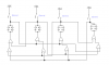
My other hobby is playing electric guitar and I have an amp with 3 channels plus reverb. At the back of my amp I have a serial connection just like the ones used for computers, 9 pin. I'm in the process of building a better footboard which will which to each channel. The 3 channels, clean, crunch, and distortion at switched by using momentary switch. I bought them a Radio Shack..(You press the switch it's on, let go, and it's off) The reverb is an on/off switch.

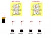
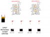
I want to buy all new switches, 3 momentary, and 1 on/off and 4 LED's. The LED's will tell me which switch I pressed so they need to light up after pressing a switch. I've read you can use relays, but I prefer to use a flip flop switch but I have no idea how to wire all this. Here is my current footboard schematic. The bottom button is the reverb.

**broken link removed**

Thanks guys...
dinkyguitar
 
Last edited:
When you say "flip flop switch", do you mean wiring up some logic behind your momentary switches, or do you mean the mechanically-latching type of switches?
 
The flip flop switch is kind of over my head...I'm getting that from another post on this forum...I tried to research first before I asked and found out that someone could use this type of switch...I think it was the 4013???

Again...this is a little over my head so if we need to start from scratch we can...

dinkyguitar
 
If you are new to all this and want a chip that takes a momentary switch and makes an output like a toggle switch check out

For $4 plus shipping you get a pre-programmed PIC chip
 
Last edited:
That might just do the trick...

Is there one that's rated for more volts?

I'm planning on using a 9v battery....or can I operate 4 LED's with this???

Another thing is...if press 1 button let's say for the clean channel and now you want to go to a distortion channel, I need the LED on the clean to turn off and then on for the distortion channel...The LED will tell you which channel you are in.

dinkyguitar
 
Last edited:
Hmmm....each button operates independently, so you would have to turn off one and then turn on another.

I have programmed PIC's to do just what you want, its an easy program, but they work at 5volts, easy enough to get with a voltage regulator (9v to 5v)
 
USE The flip flop, hook up button so it goes to the SET input of the flop you want to turn on, and TO THE RESET of each other flop to turn them off, so you don't cross circuits, then just hook the Q output of each flop to a relay, transistors are smaller but need a little math to calibrate
 
the one you have is a DUAL D-type flip flop, it should work since it still has SET and RESET,

also you will need two chips since you have 4 devices to switch and 2 flip flops per chip


acording to the data sheet the 4013 goes between 3-15V, and again just put a suiting relay across Q to ground
 
heree is basic schematic.....
 

Attachments

  • demo.png
    demo.png
    5.2 KB · Views: 606
Total flip flop NEWB needs help!!

This has been a great post, and I was hoping I could find the info I was looking for here, but I am a total NEWB to flip flop circuits. I am hopeful that someone will be able to take this just one step further and complete the attached wiring layout for me. I am attaching the layout so that a helpful circuit guru can help complete the layout. The switches shown are both normally closed or normally open, depending on which solder tabs you use. I have labeled the switches n/c and n/o to show that the "LEFT" two solder tabs (top and bottom of switch as shown) are normally closed and the "RIGHT" two solder tabs (top and bottom of switch as shown) are normally open. Thank you in advance for your help.
 

Attachments

  • 4 button momentary footswitch with flip flop leds.jpg
    4 button momentary footswitch with flip flop leds.jpg
    84 KB · Views: 380
What are you hoping to do with this setup? The OP was using a specific amp with a 9-pin socket whose contacts were temporarily shorted in pairs with some wires in common. There may have been certain voltages on those contacts, or known resistances between them which were being shunted to control internal channel-switching. Do you want to do exactly the same? If not, and all you want to do is turn on LEDs one at a time when respective switches are pressed momentarily then the circuit will be much simpler.
 
Last edited:
I want to be able to use this circuit to turn on LED's with their respective switches, and have them turn off when "ANY" other momentary switch is pressed. They will be wired to the opposite side of the switch from the amp's footswitch circuit.

This will allow me to use the circuit as a universal setup for different applications. I have searched many hours on the net for the answer to this, without success.

I also want to be able to add or subtract LED's from the circuit. In other words, if I have to wire up a single button or dual footswitch for my amp, I would like to be able to do so. If I need to wire up a 6 or 8 button footswitch, I would like to be able to do that as well.

I really appreciate any help you can offer me with this project, and I thank you, sincerely in advance for that help

What are you hoping to do with this setup? The OP was using a specific amp with a 9-pin socket whose contacts were temporarily shorted in pairs with some wires in common. There may have been certain voltages on those contacts, or known resistances between them which were being shunted to control internal channel-switching. Do you want to do exactly the same? If not, and all you want to do is turn on LEDs one at a time when respective switches are pressed momentarily then the circuit will be much simpler.
 
What you want looks do-able.
If you want a universal setup with expansion potential then your momentary action switches should be multi-pole types, e.g. at least DPDT. That will enable the amp switching function to be isolated from the LED switching function or any other function which might be added later.
The switches in your sketch look to be DPDT types. Do you have any particular footswitches in mind, and if so can you confirm they are at least DPDT?
 
Yes, they are DPDT switches, which will allow for the amp circuits to be on a separate circuit from the LED circuit at each switch. Thank you for your speedy replies. Are you the guru that will be able to complete the layout for me?

What you want looks do-able.
If you want a universal setup with expansion potential then your momentary action switches should be multi-pole types, e.g. at least DPDT. That will enable the amp switching function to be isolated from the LED switching function or any other function which might be added later.
The switches in your sketch look to be DPDT types. Do you have any particular footswitches in mind, and if so can you confirm they are at least DPDT?
 

Attachments

  • 4 button momentary footswitch with flip flop leds 2.jpg
    4 button momentary footswitch with flip flop leds 2.jpg
    80.5 KB · Views: 427
Last edited:
Ok, Letsneck, here's a circuit which should do what you want (at least, in simulation it does!) :-
LEDswitcher.gif
Resistors R7, R8, R11 are pull-downs to prevent the latch inputs floating when the switches are moving between on/off.
Switch press closes the NO contacts, sets the respective latch, and clocks 0 (present at all D inputs) into the other latches to reset them (n.b. the latch being set ignores the clock signal, which is over-ridden by the signal at the 'set' input). I have shown only three stages, but expansion to any number of stages is easy; just add the components shown in the dotted outline for each extra stage. The values of resistors R2, R4, R6 shown are for LEDs with a forward voltage of ~ 2V.
If anyone wants to play with the sim, here's the asc file for LTSpice :-
 

Attachments

  • LEDToggles.asc
    4.8 KB · Views: 229
OK, so because I do not see a value for the NPN transistors, I assume that any NPN will be fine. Also, there are no values for the D4, D7, and D8 diodes, so I assume any standard diode will be fine. The LED's do have a part number, but can I use any low voltage LED? Also, I prefer to use a 9 volt battery due to size constraints in my enclosure. Will that change the values of anything? Lastly, what chips are used? I am very new to logic type chips and the chips shown seem to be labeled differently from the 4013. Thank you
 
Any low-power NPN transistor (e.g. 2N3904), any low-power silicon diode (e.g. 1N4148) and any LED will be fine.
For a 9V supply, calculate the value (in k-ohms) of the resistor (R2, R4, R6) in series with the LED as (9-Vf)/I, where Vf is the forward voltage of the LED and I is the LED current in mA that you want (see the datasheet for the particular LEDs you use. I suggest you use a LED current less than the maximum specified, to prolong LED and battery life). Example: Vf=1.8, I = 10mA, then R = (9-1.8)/10 = 7.2/10 = .72k = 720 ohms (use the nearest standard value, either 680 or 750). The other resistor values shown are OK for 9V operation.
The chips shown in my circuit are simulated ones from the LTSpice program. The 'PRE' input corresponds to the 4013 'Set' pin, the 'CLR' input is the 4013 'Reset' pin, the 'D' input is the 4013 'Data' pin and 'CLK' is the 4013 'Clock' pin.
Make sure your 4013 is a standard 4000-series CMOS type, not a high-speed CMOS (HC) type (which can't operate at 9V).
 
Last edited:
Thank you so much for all of your help. Give me a while to order all of the parts and put this together, and I will report back to you and let you know the results. Thank you, I am very excited about this.
 
Status
Not open for further replies.

Latest threads

Back
Top