carrxarrot
New Member
I started the basics of PCB and doing schematics around 6 weeks ago in my Computer Engineering Drafting and Design class. We used EasyEDA online tool to create the SCH and PCB for our assignments/activities. Our project now is to combine the circuits that we have made before into one system so that it has multiple features. The problem is (being all honest as I can), is that I lack understanding in fundamental electrical and electronic circuits since we did everything online and no actual hands-on.
So, about my task, I need help on how I could combine these circuits into one schematic so that I could simulate it properly, and convert it into PCB and 3D output. I will also need to simulate it in other tools/softwares such as TinkerCAD.
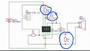
So attached below are those circuits that I made using EasyEDA, I just don't know how to properly connect them together... Do I change or modify the components themselves or change the values? I have no problem making the schematic and PCB. I just lack idea and understanding about the connections between components.
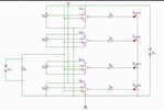
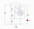
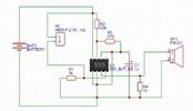
My plan is to turn my Battery Monitoring Circuit, Water Level Indicator Circuit, and Blinking LED circuit into one whole system.. As in connected together.
Also, they are simply needed to be connected together without errors (such as netlist, drc, etc.) and one thing, it doesn't need to be actually connected in a way that one circuit will respond to the other... Only simply connected as is. It's not like the water indicator responds to the battery monitor since I honestly can't find the point of connecting the two together besides this is given to us as a task. As long as the circuit is working, its fine.
Sources (the individual circuits aren't originally mine) :
https://www.electronicshub.org/water-level-alarm-using-555-timer/
https://circuitdigest.com/electronic-circuits/battery-monitor-circuit
https://www.elprocus.com/blinking-led-using-555-timer-ic/
So, about my task, I need help on how I could combine these circuits into one schematic so that I could simulate it properly, and convert it into PCB and 3D output. I will also need to simulate it in other tools/softwares such as TinkerCAD.
So attached below are those circuits that I made using EasyEDA, I just don't know how to properly connect them together... Do I change or modify the components themselves or change the values? I have no problem making the schematic and PCB. I just lack idea and understanding about the connections between components.
My plan is to turn my Battery Monitoring Circuit, Water Level Indicator Circuit, and Blinking LED circuit into one whole system.. As in connected together.
Also, they are simply needed to be connected together without errors (such as netlist, drc, etc.) and one thing, it doesn't need to be actually connected in a way that one circuit will respond to the other... Only simply connected as is. It's not like the water indicator responds to the battery monitor since I honestly can't find the point of connecting the two together besides this is given to us as a task. As long as the circuit is working, its fine.
Sources (the individual circuits aren't originally mine) :
https://www.electronicshub.org/water-level-alarm-using-555-timer/
https://circuitdigest.com/electronic-circuits/battery-monitor-circuit
https://www.elprocus.com/blinking-led-using-555-timer-ic/