Continue to Site

Welcome to our site!

Electro Tech is an online community (with over 170,000 members) who enjoy talking about and building electronic circuits, projects and gadgets. To participate you need to register. Registration is free. Click here to register now.

  • Welcome to our site! Electro Tech is an online community (with over 170,000 members) who enjoy talking about and building electronic circuits, projects and gadgets. To participate you need to register. Registration is free. Click here to register now.

How can I reverse polarity to a motor using relays?

Status
Not open for further replies.
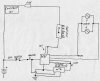
OK, so I tested the mirrors in the truck yesterday and, unfortunately, they do not terminate power. So, I will definitely have to revise the plan. But, to make life easier and not waste time and money I've already spent, I'm thinking that I can add a time delay relay [(NCTO) RL1] (between fuse and DPDT relay across the direct power feed). And add another time delay relay [(NOTO) RL2] across the ground connection (between direct ground and DPDT relay ground connections). RL1 control terminals would be wired between 12v direct, and DPDT relay grounds. RL2 control terminals would be wired between ignition feed (after switch), and direct ground. No power in circuit until ignition is turned on. Ign on energizes the DPDT relay and RL2 (which closes ground and allows RL1 to energize). Power runs to mirror and it extends. Time delay opens RL1 after, lets say 5 seconds, and circuit de-energizes. Once vehicle is turned off, RL1 resets, energizing the circuit and causing mirrors to retract. After 5 seconds RL2 resets, de-energizing the circuit once more, and hopefully all is well with the world! Do you think this will work okay?
 

Attachments

  • My Mirror Schematic001.jpg
    My Mirror Schematic001.jpg
    1.4 MB · Views: 259
Last edited:
If that's what your going to have to do, then that's what your going to have to do.

Are you sure there is no limit switch or pulse/direction info available for position?

They probably have an overrun clutch on the mirror motor drive?
 
I measured 1.64 amps between a mirror lead and ground once the mirror reached its designated position. I also tapped the mirror return lead to ground a few times and it sparked each time. That's all I could think of to do as far as testing goes. I didn't want to maintain power to the mirror too long, lest I burn out the motor. I left a voicemail at Kool Vue (mirror manufacturer), explaining the situation and asking for someone to get back to me to let me know if the mirrors terminate power of not. That was about 6 days ago. I'll try again tomorrow. But thus far, it seems that they don't terminate. And it sucks because I literally have the relay and wiring soldered up and ready to install! Nice and neat too!!!
 
I also thought about using a DEI power window auto up/down module. But I figured since I've already invested time and $, I might as well just finish what I started. Its also proving difficult to find a 12v time delay relay. And none of the Google results seem to completely specify the type of time-delay relay (NOTO, NOTC, NCTO, NCTC)!! This is becoming a pain!!! The one good thing is that I'm learning and relearning as I go along. That I like! Still a pain though!!! :)
 
I found this application note: Look at www.te.com, under polyswitch, application notes, automotive, driver-side. I can't paste link directly for some reason. That's how they protect the switches/motors.
 
I figured I'd post this for others viewing this thread in the future.
 

Attachments

  • Tyco_Automotive_DriverSide_Control_Switch.pdf
    2 MB · Views: 495
Last edited:
This is a cool device but I don't think it fits my particular application. From what I understand, the polyswitch has to heat up in order to increase resistance and restrict current. Then once then fault is resolved, it cools off and allows normal current flow. Well, lets say normal current flow is 1 amp to operate the mirrors. That means current is flowing to the mirror motors until it creates enough heat to activate the polyswitch. Then the polyswitch will cool off and allow current flow until it heats up enough to activate again. This process will happen continuously until the vehicle is shut off. Then the polyswitch will have to cool off once more, before it will allow current to flow, and the mirrors to fold in. This could take (I would guesstimate) up to about a minute to happen. Thus, still damaging the mirror motors. So, a polyswitch is not really feasible IMO. Please correct me if I'm wrong though.
 
What I need is a DPDT time delay on make "and" break relay. I don't believe I'll be lucky enough to find one though. That would be too perfect!!! Matter of fact, no that wouldn't work...
 
Last edited:
The polyswitch is worthwhile protection nonetheless. Firefox went nuts on me. After I restarted FF, it was Ok again. I couldn't copy links,
 
Yeah, FF wigs out on me from time-to-time also. I guess your right. A polyswitch in the circuit would be a nice alternative to a fuse. What do you think, about 2A?
 
Cool. Yeah I checked out SSAC. They're waaaayyyy to expensive. $89. There out of their freakin minds!! Debating on trying to build a SS dual timer. Don't know how to design that type of circuit though. Can you help me with that? Oh! Did you see anything wrong with my relay circuit? I'd like to know so it can at least be an option if I decide to go that way.
 
Although I haven't used these parts, I want you to look here, here and here. **broken link removed**, www.cpustick.com, www.comfilech.com

The first uses the CPUSTICK OS. The last is BASIC. You can download an emulator for the CPUSTICK OS.

With all you have to do, I really don't suggest a bunch of timers. A general purpose CPU, I think makes more sense.

With a few H bridges and some High side current measuring IC's and probably some inputs and your there. You could add an LCD easily with the BASIC module and go from there. You could try the straight timer mode, but you could add a RESET mode, where the system would go toward a limit. Stop, reverse direction and go to the requested position. Limits could easily be achieved and it would solve all of your problems except perfect positioning.

The way systems are designed is you have two limit switches and an ORIGIN switch. The ORIGIN switch is very precise. The idea is that the system heads toward the org switch, passes it, stops, reverses and SLOWLY moves until ORG is found and stops. With steppers, you can pulse the required number of times. Servo motors require n encoder.

Any way, I'd bite the bullet and go for a processor based approach. Those three don't seem hard and they don't require a development kit. The hard part will be getting everything to move at once. When I did a gantry crane for a model railroad using the 1802 processor, it was nearly impossible to get both axis to move at once. I was able to do so using BASIC. This was 30+ years ago.
 
That stuff is way beyond me! I'm just going to try and build the timer circuit. A tech is trying to help out with this matter and posted this video on youtube to show me how simple it is:[video]http://youtu.be/C0Q02pww3kw[/video].

What do you think?
 
I can build it. My problem comes with designing the circuit. I can fix things all day as long as I know what the problem is. Been doing that since as long as I can remember. I'm a tinkerer. Went to electronic school for about a month back in the early 90's. Circuit design and diagnosis beyond ABC is beyond my expertise though. I love this learning and relearning process! But past a certain point, its no longer practical because of time and financial constraints. So, for me its baby steps. As far as the relay circuit, I only need the 2 timers. But I need the circuit as small as possible due to positioning in the vehicle. I think I can get the YouTube circuit to fit onto a 2x2 inch board. Just bought some of the components earlier today. Radio Shack is the worst electronics parts store on the planet because they don't carry crap! So I'm going to try a another store I know of, and hope that they have everything else I need.
 
Status
Not open for further replies.

Latest threads

New Articles From Microcontroller Tips

Back
Top