Continue to Site

Welcome to our site!

Electro Tech is an online community (with over 170,000 members) who enjoy talking about and building electronic circuits, projects and gadgets. To participate you need to register. Registration is free. Click here to register now.

  • Welcome to our site! Electro Tech is an online community (with over 170,000 members) who enjoy talking about and building electronic circuits, projects and gadgets. To participate you need to register. Registration is free. Click here to register now.

How can I reverse polarity to a motor using relays?

Status
Not open for further replies.
A lot depends on the mirror interface. One could ASSUME it act's like a wiper motor. A nudge causes the motor to move, which closes a switch until the motor makes a full swipe of the window.

Questions such as: 1) are there only two positions? Retracted and extended or is there an "adjust mode"? Does this thing draw power all the time?

Assuming: 1) polarity causes a reversal and no power is drawn at either extreme such that you can connect this safely to the ACC terminal and 2) A pulse is required for position A and B.

A delay on Make (IGN ON) could extend the mirrors on startup.
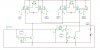
The retract will be harder because you need a delayed source of power. A 200 Impalla has just that: Radio/windows continue to operate until the door is opened. You may be able to mimic this easily by using a dual coil latching relay.

IGN would energize the set relay and disable the reset coil.
A door switch would be installed such that it is on when opened. That would operate the reset coil. You then have a source of delayed power until you open the door.

Another way is a low power microprocessor.
 
Yes, there are only 2 positions. 2 wires control the retract and extend motor. I could MAKE them adjustable of course. That's simple enough. But it doesn't really make sense to do so. Also, yes I have the delayed power like the Impala u speak of. I have a 2004 Chevy Trailblazer. I have considered this option also. But thought about a passenger exiting the vehicle before the mirrors completely retract and disrupting the power.
 
So, two total wires where you have to maintain the polarity until the mirror stops and no power is drawn at either extreme?

Check you car and see if the OFF only works when the driver's door is opened?

So, I think this could work (without the nudge)
1. a DPDT relay that reverses power, the NC position means retracted. Coil power through ACC circuit. Mirror power through BAT (always on)
2. An SPDT relay whose coil is energised in the IGN position (call this IGN inhibit)
3. A dual coil latching relay. contact completes coil circuit in #1, (SET position) ----> ACC opens mirrors

The Reset coil
Pulse it, if IGN just turned OFF and on Delayed power. Power from the delayed power signal. You might be able to use an optoisolator and a multifunction timer.

The dual coil latching relay doesn't require power to maintain a state. It requires a pulse with the proper polarity. One coil can be on continuously with no harm. reversing the coil polarity will also change it's state.
 
Ok. I'm trying to follow ur explanation as best I can. I'm doing moderately well but some of it is flying over my head. Please be patient with me. I want the mirrors to extract when I turn the vehicle on, but I can live with them extracting through ACC power if that simplifies things. And I'm not sure what you mean when you say "Check you car and see if the OFF only works when the driver's door is opened?". The delayed power for radio and windows is in effect once you turn the vehicle off, until a door is opened, then delayed power is terminated. When I speak of the "nudge", I mean a manual option on top of the auto-folding. I saw somewhere that the existing mirror controller can be used to accomplish this when its in the neutral position, controlling neither left nor right mirror. If possible, can u post a schematic with ur explanation? It may help me follow things a little better. I'm not great at reading them, but together they may help my slow comprehension...
 
excerpt from ALLDATAdiy.com


Fold motor in each of the outside mirrors, if equipped with power fold mirrors-Provides extend and retract movements of the mirror and is serviced as a complete mirror assembly Each of the outside power mirrors contains 2 reversible motors to provide horizontal and vertical movement of the mirror glass. The vertical motor operates the up and down directions and the horizontal motor operates the left and right directions. If equipped with power folding mirrors, each outside power mirror will contain a reversible fold motor to operate the extend and retract functions. Each of the mirror motors are circuit breaker protected.

Power Mirror System Controls
The power mirror switch incorporates a 3-position mirror select switch and a 4-position mirror direction switch. The mirror select switch allows the operator to select the mirror to be moved by rotating counterclockwise to the L position for the left power mirror, rotating clockwise to the R position for the right power mirror, or the center which is the neutral/fold position. The mirror direction switch is a 4-position switch that allows the operator to move the selected mirror up, down, left, or right. The mirror direction switch also functions as the folding mirror switch. When the selector switch is in the neutral/fold position, activate the mirror direction switch to the left to extend the mirrors and right to retract the mirrors.

FOLDING MIRROR SYSTEM

Folding Mirror System Controls

When the mirror select switch is in the neutral/fold position, it allows the operator to retract or extend the outside rearview mirrors from a single switch. The mirror fold switch incorporates solid state circuitry to allow this single switch input to alternately perform both extend and retract functions.

Folding Mirror System Operation

The mirror fold switch receives power through the battery supply voltage circuit and the EXT LPS fuse and a constant ground. The mirror extend and retract control circuits are connected to ground through the normally closed contacts of the mirror fold switch. When the mirror fold switch is activated, the solid state circuitry will energize either the extend or retract relay, depending on the last function, which supplies battery voltage to the fold motor through one of the control circuits. The other control circuit is connected to ground through the normally closed contacts in the mirror fold switch and the mirror extends or retracts.
 
I guess this is the explanation of how the mirrors work when installed on my vehicle model that comes equipped with power mirrors (which I hear only exist in Europe). Mine, however, needs to be moded to use the folding feature. Very frustrating!!!
 
OK, the mirror positioning is conventional. One switch to select L OFF and R and a joystick like control for positioning.

The retracting explanation seems confusing. It does say that the folding power is supplied by the battery always on power source) which makes sense.

It appears that a momentary push of a normally closed switch reverses the last position. If this is true, it could make things difficult because you don't have an OPEN and CLOSE function. Using contact closures to ground is a standard control technique. Because of the solid state controller, all you had to do is to pulse the switch.

It thows most of what I said earlier out the window because it was based on reversing the polarity.
 
The polarity reversal is a definite. It's not speculation on my part, I've actually tested it by supplying 12v to the mirror and then reversing the polarity. I wanted too make sure they were the correct mirrors and that they worked. I could easily hook up a simple circuit without relays using a DPDT polarity reversal switch. But then there would be no auto extend/retract on ACC or ignition. Plus I'm trying to use the mirror switch that's already in place. I would HATE to murder the Cool Factor of having these mirrors! I'm gonna sit down and try to design a laymans circuit for what I want. I've just been too busy to concentrate on it. My world is kind of burning right now, if you know what I mean. Lots and lots of pressure and BS on my mind. The other issue is that I've been away from electronics this in depth for a long time. I have to relearn some of the little bit I did know, as well as learn a few new things. I really don't know if my brain can take it at this point, but I'm stubborn and refuse to let something this trite beat me!!! But I can sure use some help!!! :)
 
OK, I'll see what I can do to help.

I'll point you here http://search.digikey.com/scripts/DkSearch/dksus.dll?Detail&name=306-1238-ND Look at the datasheet.

This wasn't the timer I was thinking of, but it gives you the idea of a part of the functionality that I think is required. **broken link removed** There are others, that's smaller.

Just get a handle on how dual coil latching relays work and 12V monostable timers that can be triggered on a rising or falling edge. True, the 555 timer could probably do it. True, a microprocessor solution to the logic is also possible. For now, I'll try to concentrate on building something with common parts.

Also, the retract supply has to be from a BATTERY (always on source) and we are assuming that zero current gets drawn from the retract leads once it's in the desired position. i.e. We supply power forever for each direction. When the retract or extend is complete, zero power is drawn from these terminals. Am I also assuming that these terminals are directly connected to the motor and not a control signal? What kind of current are we talking about?
 
The mirror retract turns out to be surprising simple. That what I usually do, is make it complicated at first and then simplify.

The attached isn't quite a schematic, but a sort of schematic/block diagram. Basically a DPDT relay is configured so that when it's normally closed power is appled to the motor so that it retracts. e.g. when the coil is not powered, the motor will retract. The motor is supplied with fused battery power.

Another relay basically detects whether the engine is on. It could come the ECM fuse. When the engine is on, the DPDT relay switches state and the motor extends.

No power would be drawn when the motor is set to retract.

Manual control of the mirrors could be implemented with an auto/on switch and an extend/retract switch. The latter only works in manual mode. These switches would be inserted at the AB position in the diagram.
 

Attachments

  • Mirror Retract 001.pdf
    17.3 KB · Views: 263
Cooooolllll!!!! That's along the same lines as I was thinking. I was told that the following circuit will also work. Please let me know what you think. And whether there is a big difference between it and the simplicity of your circuit.

[Simple relays circuit so the mirrors open when the car comes on and closes them when the car is off...]
 

Attachments

  • Folding mirrors circuit.JPG
    Folding mirrors circuit.JPG
    100.9 KB · Views: 294
I though you would already have a left mirror/off/right mirror select switch and an up/down/left/right movement switch. How do you kbow the mirrors will go back to the same position each time? I'm not sure how well time will work. On at least one of my cars, you could go and push the mirror physically. so, someone bumps the mirror and it's off again. Watch leakage paths with the semiconductors.

And somehow you have a retract/extend motor.
 
That IS a concern. The mirrors can be manually adjusted, so yeah, I have NO idea how I would get the mirrors to return to the appropriate position if shifted manually. Figured that would be something that I may just have to live with. I'm so lost right now...
 
Re: Thermal switch circuit

Can I beg your assistance again? I built a power center for my truck. Basically its a box for 2 amplifiers, with 8 cooling fans. I'm trying to put 2gether a circuit that will make the fans cut on only when the box temperature reaches a certain degree. I'm trying to find out what components I need. I saw some schematics online (http://www.bcae1.com/coolfans.htm), but I'm hoping it can be dumbed down for the electronically impaired. Think u can help me with this?
 
You could make it easier on yourself if you want something adjustable and start out with something like http://www.analog.com/en/mems-sensors/trip-point-sensors-digital/ad22105/products/product.html available from digikey for a few bucks. Add a 5V regulator and whatever support it needs. Use a pull-up and an N-channel MOSFET to turn on the fan with inductive kickback diodes on the fan.

Or that circuit above.

Or just buy one: **broken link removed**

That would be really simple.
 
Thermal switch circuit

DUDE! I Freakin Luv U And This Site!!! I'm going to try and find that switch in the US. Thanx again for the help!!! But now for the bad news... I began doing the wiring for the Folding Mirror Circuit. Not in the vehicle, just soldering and shrink tubing everything together (All done!). I wanted to make sure that the mirrors terminate power once they reach their designated position. I didn't have a 12v power supply on hand. Just a 9v, which read 13v on a DMM (go figure). I tried it and the motor worked, but not fully. So, I have to wait until later to test it again. BUT, the mirror did seem to whine (and it clicked!!!) when in an extended position, giving me the inkling that they may not terminate power after all. What will I have to do if I confirm that power doesn't terminate? Are 2 timer relays in the circuit my only option? Does a DPDT timer relay exist to make life easier? Maaaaannnnn, I really hope these things terminate, cause this is getting complicated!!!
 
Status
Not open for further replies.

New Articles From Microcontroller Tips

Back
Top