Hey spec,
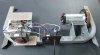
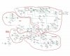
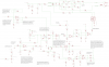
This particular one looks like a PWM system, although can't find a schematic, so no way to tell for sure. And you're right in that current would be steady and over heating would be a problem.
But you bring up an interesting thought.
How about leave the console attached? Take the whole rig (PCB - without its current facade - and motor) re-mount it all and mate it to the lathe, I guess. Then you'd have a control panel with at least some manner of readout to convert to spindle speed. I kind of like that idea

.

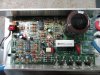
 ) is to apply, very slowly, a gradually increasing test voltage (bias) to the gate of the IGBT, thereby gradually increasing the voltage/current going to the motor.
 .
.")
 . And I had no idea the old treadmill guts went for so cheap!
 )to learn electronics 101 just to get the controller running. I have a cheap 555 circuit tho. Tested it on the controller by wiring the positive pole to the IGBT gate. It resulted the same as the 10k ohm pot failure. I don't know what I'm doing wrong.