Continue to Site

Welcome to our site!

Electro Tech is an online community (with over 170,000 members) who enjoy talking about and building electronic circuits, projects and gadgets. To participate you need to register. Registration is free. Click here to register now.

  • Welcome to our site! Electro Tech is an online community (with over 170,000 members) who enjoy talking about and building electronic circuits, projects and gadgets. To participate you need to register. Registration is free. Click here to register now.

High pass filter to block out 60Hz signal

Status
Not open for further replies.

davids85

New Member
Hello, I'm a graduate student working in geology and geophysics and (an unfortunately small) part of my thesis is to develop a seismic acquisition system to grab signals in the range of 1kHz to 20kHz.

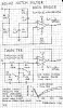
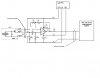
I've built an amplifier around the LT1115 to amplify the signal from accelerometers and have run into a myriad of issues, most of which have been resolved (likely due to poor ground planes). My last major challenge is a 60Hz signal, which I'm assuming is induction from wall line from the other (commercial) amplifiers I'm using or something along those lines. What I've found is that my 1kHz to 20kHz signal rides on top of the 60Hz signal, which ordinarily wouldn't be a problem, but the inducted? 60Hz in some areas seems to be amplified to my maximum voltage of +/-10v, thus often destroying my higher frequency signal.

My questions are: does it make sense that I could be amplifying a 60Hz signal even though I believe I do not have any 60Hz signal electrically(physically?) connected to my system. The LT1115 circuit supposedly amplifies ~100 times (in reality it's more like 50) and an audio amplifier adds another 10 fold gain and by that point I'm partially blasting out of +/-10v. I've noticed when I have an oscilloscope hooked up to nothing in my lab I see a 60Hz signal in the range of 25mV. Nearly all of my wire for my amplifiers/accelerometers is shielded and twisted.

And are there better resistor capacitor pairs than others for just doing a standard high pass filter? I tried a 1uF cap and a 100ohm resistor in a high pass formation and it seems to get rid of 60 Hz noise, though I am a bit nervous about the other signal it might be killing off as the 1/2(pi)RC for the pair is 1.5kHz as well as some inconsistent phase shift it might produce if I use the same filter with components that have varying tolerances on 8 separate channels. Is there a better way to do a high pass filter where you don't have to worry about a phase shift?

Last one, it seemed like when I used my high pass filter between the accelerometers at the amplifier, I got nothing (60Hz or 10kHz). I didn't test that in depth with other amplifiers, so there could have been something else wrong, but does that make sense at all?
 
Last edited:
A single capacitor feeding a resistor is a very simple highpass filter with a very low amount of reduction of lower frequencies. It is a first order filter.
A second order filter cuts lower frequencies twice as much.
A third order filter has three RC networks with isolation amplifiers in between and is even better.
Forth-order and fifth order filters are even better.
 
Oooh geology, my favorite hobby, see my website. Anyways Can you post a rough sketch of your system blocks so we can get a better picture of what you have. So the accelerometers are used to detect the seismic activity? Are these wired via single ended lines, are these real long wires? Is this thing battery powered? Are you testing out in the field or in a lab.


Assuming that you do in fact need a filter (Which might be a good idea just because) you might want to look into a bessel active high pass filter function as it has a good phase response.
**broken link removed**
 
Or use a **broken link removed**
 
I am still curious as to the 60Hz pickup as this should not be a real issue if system is made correctly. Something must not be right, I am just having trouble thinking what it might be without a diagram or at least more info. Hmm. What do you think MikeMi?
 
Last edited:
From Forrest Mims mini-notebook Op-amp IC circuits.

Sorry about the quality.
 

Attachments

  • 60Hz notch..PNG
    60Hz notch..PNG
    34.6 KB · Views: 1,573
a seismic acquisition system to grab signals in the range of 1kHz to 20kHz.
My first thought was that these were rather high frequencies for seismic signals, but then I am not experienced in that area.

I've built an amplifier around the LT1115 to amplify the signal from accelerometers ...
My last major challenge is a 60Hz signal, which I'm assuming is induction from wall line from the other (commercial) amplifiers I'm using or something along those lines.

My questions are: does it make sense that I could be amplifying a 60Hz signal even though I believe I do not have any 60Hz signal electrically(physically?) connected to my system.
Yes, in a busy wired-up building there are usually mains frequency magnetic fields everywhere

The LT1115 circuit supposedly amplifies ~100 times (in reality it's more like 50) and an audio amplifier adds another 10 fold gain and by that point I'm partially blasting out of +/-10v. I've noticed when I have an oscilloscope hooked up to nothing in my lab I see a 60Hz signal in the range of 25mV. Nearly all of my wire for my amplifiers/accelerometers is shielded and twisted.
Lots of gain there but how is it disposed?
I am guessing that the system is built as:

Code:
Accelerometer -----------long wires----------- LT1115--audio amp--display
 
It would be much better to build it like this:
 
Accelerometer--LT1115-----------long wires-------------audio amp--display
So that any noise induced into the long lines is a small compared with the required signal.


And are there better resistor capacitor pairs than others for just doing a standard high pass filter? I tried a 1uF cap and a 100ohm resistor in a high pass formation and it seems to get rid of 60 Hz noise, though I am a bit nervous about the other signal it might be killing off as the 1/2(pi)RC for the pair is 1.5kHz as well as some inconsistent phase shift it might produce if I use the same filter with components that have varying tolerances on 8 separate channels. Is there a better way to do a high pass filter where you don't have to worry about a phase shift?

There are many possible combination of R and C which will give a suitable high pass response.
However, as you have added:
Last one, it seemed like when I used my high pass filter between the accelerometers at the amplifier, I got nothing (60Hz or 10kHz). I didn't test that in depth with other amplifiers, so there could have been something else wrong, but does that make sense at all?
It could be that the RC filter is loading the output of the accelerometer and attenuating the required signal.
What sort of accelerometer are you using?
If it is a piezo electric type, you really do need the amplifier close to the accelerometer, the output from the piezo will be a high impedance and the 100ohms of your RC filter will severely attenuate the output.

JimB
 
Wow so many replies! Thank you. I'm sorry for the late response, I've been away at an oil industry competition where my team won 3rd place!

The system basically looks like this: accelerometer (which includes a JFET) -> 1m of twisted shielded wire -> LT1115 amplifying circuit -> longer twisted/shielded pair to audio amp -> digital acquisition card. Most wires aren't longer than a meter, but some are wound in circle... maybe making a good inductor.

An older version of the schematic is attached (I don't have an updated one at school). Basically we added a high pass filter on the positive voltage line for the JFET and changed Rhp to 220k from 2meg. We've had some serious challenges where I think the LT1115s became saturated. That issue is more or less solved I think.

I tried the 2nd and 3rd order filters as recommended and they work nicely. For now I'll be sticking with the quickest, simplest solutions because of time. My adviser would prefer I change the filter to operate before the signal reaches the LT1115 amplifier. There is a JFET in the accelerometer as well as an "input bias current?" on the LT1115. (I'm not sure if I'm using the correct term). I likely accidentally messed up current going to the accelerometer by trying to place a high pass filter before the LT1115 earlier and that's why the system stopped responding appropriately.

I do have a question about how to make sure I use the right resistances to create a second or third order high pass filter going into the LT1115 while making sure the voltages are correct. If I'm currently using a 220kohm resistor and the input bias current is 50nA, how would I determine the correct resistors to do:
sig>---||----||----||---- sig>
| | |
Res Res Res
| | |
Gnd Gnd Gnd

I would agree that intuitively it would seem like inductance shouldn't be quite a big deal if the system is grounded appropriately (and I think it is). I think it's reasonable that we're seeing an inducted signal because I can see one on my oscilloscope when nothing is connected and we're theoretically gaining about 100x (so if it were a millivolt or so it could become significant pretty easily).

For reference, we are working in the kilohertz range because the experiment we're working on is a model. Normal seismic is in the 30Hz range (+/- some depending on the application - earthquakes are probably very low relative to that and some seismic could be in the hundreds of hertz).
 

Attachments

  • ACH-01 signal conditioner2.pdf
    211.4 KB · Views: 446
Last edited:
Without actually looking at your setup it is difficult to advise further.

However, I have had a look at you LT1115 circuit and re drawn it a bit. Some of it may seem a bit pedantic but in its original form it was a bit obscure, going on bizarre in certain areas, notably the power supply. I am at a loss to understand what that actually represented!

I have tried to show how I would connect things up as a system to minimise noise.

JimB
 

Attachments

  • Accel Amplifier..JPG
    Accel Amplifier..JPG
    56.7 KB · Views: 542
  • Accel PSU..JPG
    Accel PSU..JPG
    26.8 KB · Views: 472
Without actually looking at your setup it is difficult to advise further.

However, I have had a look at you LT1115 circuit and re drawn it a bit. Some of it may seem a bit pedantic but in its original form it was a bit obscure, going on bizarre in certain areas, notably the power supply. I am at a loss to understand what that actually represented!

I have tried to show how I would connect things up as a system to minimise noise.

JimB

I think your redrawn version of the circuit is accurate, yes.
The power supply, as I'm told, has the capacitors because they more readily provide current than do batteries. That part of the circuit is something my adviser designed from someone's advice with a stronger background in electronics than my adviser or I have.

The wires you recommended to twist are twisted along the majority of the wire, with 5 or 6 inches more or less exposed at one point.

I figure chances are high I'm going to have this 60 Hz noise no matter what and I'm going to have to filter it. Do you have any ideas on how to create an equivalent resistance (or create an equivalent voltage?) to create a 2 or 3 stage filter right before the signal reaches the LT1115? That's really where I'm stuck.

Can you consider a filter like: (ok the resistors and ground won't move to the right place, but basically a 2nd order high pass filter)
sig in---Cap----Cap----sig out
| |
R1 R2
| |
gnd gnd

the same as (again resistors and ground won't move to the right place, 1st order high pass filter)
sig in---Cap---sig out
|
R3
|
gnd

where 1/R3 = 1/R1 + 1/R2

I think I need to make sure I have an acceptable voltage level coming in to the LT1115 input and I think I determine that with a resistor to ground off the signal wire... hopefully that makes some sense. I'm still pretty sketchy on it myself.
 
Last edited:
Twisted wires are used with a signal that is completely balanced like telephone lines. Your signal is not balanced so you should use shielded audio cable.
Your "highpass filter" is simply one capacitor and one resistor that has such a gradual slope that you will have plenty of 60Hz hum.

If you simply connect a capacitor to a resistor and another capacitor to another resistor then the sections affect each other and cause a very droopy response. Instead you should make a Sallen and Key Butterworth highpass filter with 2 or 3 sections. Look in Google. It uses one opamp which you already have.
 
if you have a high gain amp stage it will pick up the mains too, try putting your finger on a scope probe: you will see an almost perfect sine wave of exactly 50/60 Hz depending on which side of the continent you live on
 
if you have a high gain amp stage it will pick up the mains too, try putting your finger on a scope probe: you will see an almost perfect sine wave of exactly 50/60 Hz depending on which side of the continent you live on

I've noticed a rather ugly 60 hz sin wave when I put my finger on a side of the scope probe and even if I just put my hand around a probe (capacitance??). Does that serve as good evidence that I could easily be picking up some noise from the mains?
 
My record player and tape deck (remember them?) use preamps with very high gain especially at frequencies down to 20Hz and are unbalanced like yours but have no hum. The cable is inexpensive and small shielded audio cable.
 
I've noticed a rather ugly 60 hz sin wave when I put my finger on a side of the scope probe and even if I just put my hand around a probe (capacitance??). Does that serve as good evidence that I could easily be picking up some noise from the mains?

you certainly are, I gather 2-3 volts on my body and got a few volts out of a large sheet of metal I keep on my bench at work
 
If you simply connect a capacitor to a resistor and another capacitor to another resistor then the sections affect each other and cause a very droopy response. Instead you should make a Sallen and Key Butterworth highpass filter with 2 or 3 sections. Look in Google. It uses one opamp which you already have.

I think you mentioned early in the thread that creating a 2nd or 3rd order high pass filter where, as I understand it, have a filter then have a second filter filtering that filter, etc... should eliminate the high frequency noise and it seemed to work well. Do you think it would also have a strong response on higher frequencies (2 orders of magnitude higher)?

If you think it would just have a droopy response on the 60Hz that's fine. I was using values for 120Hz (if my math is right, 1kohm resistor and 1uF cap). If the 60 Hz still exists it's ok; it will be filtered out with computer processing, it just needs to be significantly diminished from what it is now because it is exceeding the maximum voltage of my amplifiers and effectively eliminating the signals I'm interested in.

It would be preferable to use high pass filters over building a complete circuit (granted it's an easy circuit to build and it's well documented). I think the circuit you recommend is only for 3dB as well? I probably need to knock it down quite a bit.
 
My record player and tape deck (remember them?) use preamps with very high gain especially at frequencies down to 20Hz and are unbalanced like yours but have no hum. The cable is inexpensive and small shielded audio cable.

Ah, and for the record, we are using twisted shielded audio wire, but a 5/6 inches of the wire is exposed and is not twisted. Do you think trying to bring it down to a couple inches would make the difference?
 
I think you mentioned early in the thread that creating a 2nd or 3rd order high pass filter where, as I understand it, have a filter then have a second filter filtering that filter, etc... should eliminate the high frequency noise and it seemed to work well. Do you think it would also have a strong response on higher frequencies (2 orders of magnitude higher)?

If you think it would just have a droopy response on the 60Hz that's fine. I was using values for 120Hz (if my math is right, 1kohm resistor and 1uF cap). If the 60 Hz still exists it's ok; it will be filtered out with computer processing, it just needs to be significantly diminished from what it is now because it is exceeding the maximum voltage of my amplifiers and effectively eliminating the signals I'm interested in.

It would be preferable to use high pass filters over building a complete circuit (granted it's an easy circuit to build and it's well documented). I think the circuit you recommend is only for 3dB as well? I probably need to knock it down quite a bit.

Do you have an oscilloscope, if you do it may well be worth plaing around a bit, your entire circuiit needs to be inside a steel case idealy as that will help stop picking up the signal in the first place particularly after the filcer circuit
 
I think you mentioned early in the thread that creating a 2nd or 3rd order high pass filter where, as I understand it, have a filter then have a second filter filtering that filter, etc... should eliminate the high frequency noise and it seemed to work well. Do you think it would also have a strong response on higher frequencies (2 orders of magnitude higher)?
A highpass filter passes high frequencies and blocks low frequencies. It has no effect on high frequency noise.

If you think it would just have a droopy response on the 60Hz that's fine.
Three RC sections connected together have a loss of -29dB at the calculated cutoff frequency. It is droopy so if the calculated frequency is 480Hz then 60Hz will not be reduced much but 4.8kHz and even 9.6kHz will also be reduced a little. A Sallen and Key Butterworth 3 section highpass filter calculated at 480Hz has 480Hz with a loss of only -3db and 60Hz will be reduced -54dB which is 1/500th. Frequencies above 1kHz will not be reduced.

It would be preferable to use high pass filters over building a complete circuit (granted it's an easy circuit to build and it's well documented). I think the circuit you recommend is only for 3dB as well?
A 3-section Sallen and Key Butterworth highpass filter is -3db at the calculated cutoff frequency then sharply drops at -18dB/octave. It uses three resistors and capacitors with the opamp you have now.

Ah, and for the record, we are using twisted shielded audio wire, but a 5/6 inches of the wire is exposed and is not twisted. Do you think trying to bring it down to a couple inches would make the difference?
My record player and tape deck had half an inch of wires but had no hum. Maybe yours is connected wrong. Maybe hum comes from your power supply.
 
Status
Not open for further replies.

Latest threads

New Articles From Microcontroller Tips

Back
Top