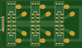
I would like to make an 8-channel antenna switch, usable only two at a time.
It should work like this:
the inputs (radio) and the outputs (antennas) are set in any combination of the 8 connectors.
For simplicity I call them C1 ... C8 (Channel 1 ... Channel 8)
Eg:
I set that the radios are [C1] and [C2] while the antennas are {C3-C8}
I want to use radio1 [C1] with antenna {C3} or with antenna {C7}, or I want to use radio2 [C2] with antenna {C3} or with antenna {C5} and so on.
But I might want to set the radios to be [C1], [C2], [C3], [C4] and they remain only for the {C5-C8} antennas.
The operating frequency should go from 1MHz up to 70MHz better if it could go up to 146MHz.
The power involved ranges from 5W up to 2KW.
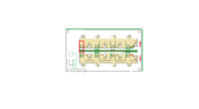
The relays that I think are suitable for this purpose are these OMRON G2RL-1-E 12V DC which have two 16A contacts in parallel. They are relays that are usually used for this purpose, in the sense that I have seen them in other antenna switches.
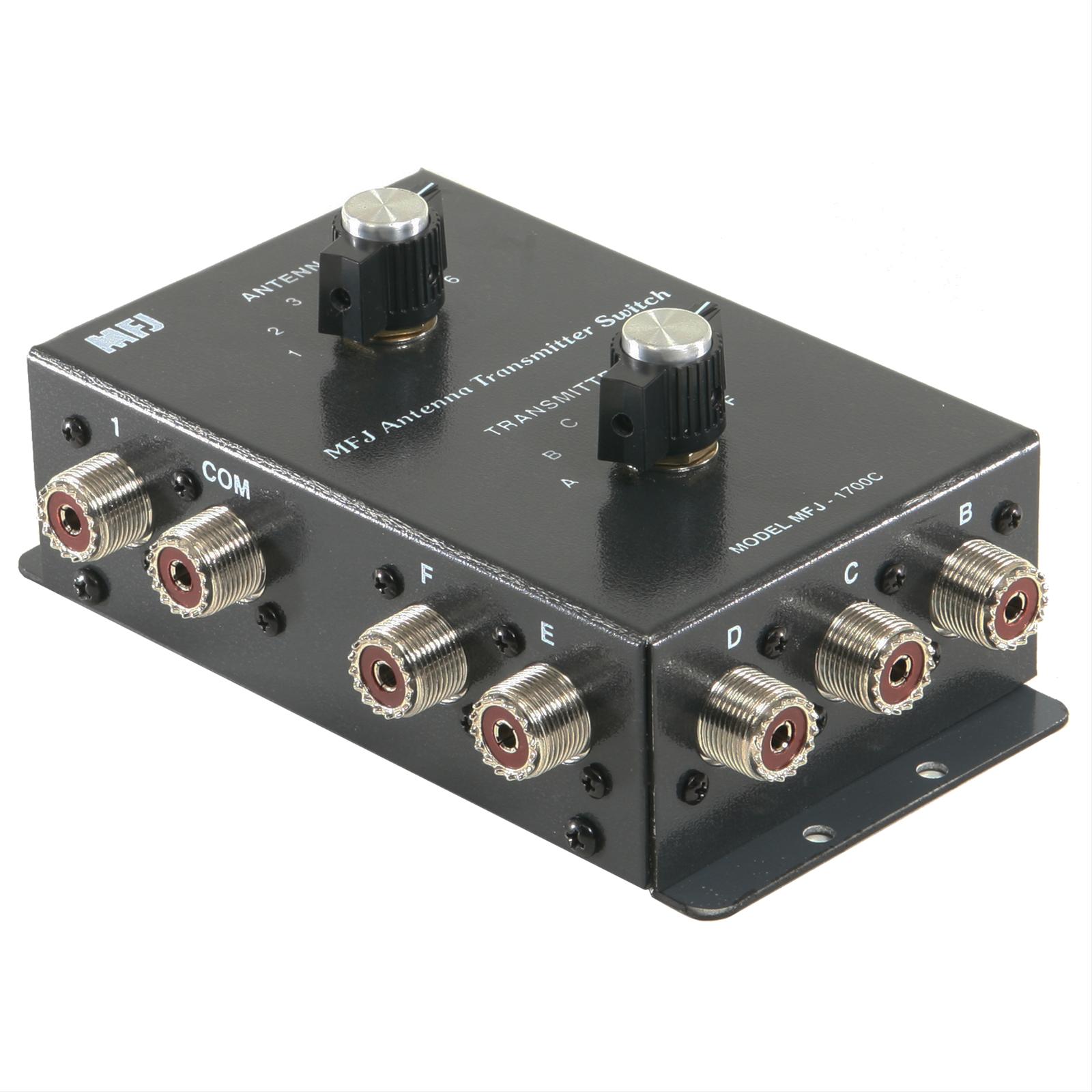
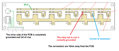
The connectors are from SO239 which are soldered (the central) directly to the PCB.
The connectors not in use have the central connector connected to ground.
While those in use connect the connector to the 50 Ohm track.
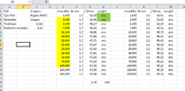
My problem is not only being able to calculate the sizing of the tracks but understanding how the contacts of the relays and connectors affect the overall impedance. That way I should be able to correct everything.
I am looking for some saint with great patience, able to help me and solve this problem.
