Continue to Site

Welcome to our site!

Electro Tech is an online community (with over 170,000 members) who enjoy talking about and building electronic circuits, projects and gadgets. To participate you need to register. Registration is free. Click here to register now.

  • Welcome to our site! Electro Tech is an online community (with over 170,000 members) who enjoy talking about and building electronic circuits, projects and gadgets. To participate you need to register. Registration is free. Click here to register now.

LTSpice voltage controlled switch always stays on

Status
Not open for further replies.

Fluffyboii

Active Member
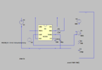
Hi, I am trying to make a simple pre-charge circuit as a small test project. What I am trying to do is make a circuit that charges the 320u capacitor that is series with a 50k resistor until it gets full, after that it disconnects it from 400V supply but it also disconnects it if a certain amount of time passes before it fully charges. Anyway I will use 555 in monostable mode to put the timer and use a comparator and a reference voltage to monitor the voltage and put both of them as input to an inverted "or" gate or something like that so when one if them is completed the relay (voltage controlled switch in this case) will close. Only problem is the voltage controlled switch is always stuck closed and capacitor starts from 400V so I can not see any charging curve or whatsoever. The 555 part works fine and creates a 0.5ms output pulse from pin 3 directly connected directly to the voltage controlled switch so I can't figure out why it doesn't work.
 

Attachments

  • precharge.asc
    2 KB · Views: 236
  • Screenshot_1.png
    Screenshot_1.png
    19.6 KB · Views: 316
Top menu, right side, "Help"
Search for "switch"
Drop down to "S" Voltage controlled switch.
you need to enter parameters for the switch.
What voltage is on, What voltage is off, internal resistance. etc.
 
Here's the simulation for the corrected circuit:

You need to add the SW definition as ronsimpson suggested.

Also use the startup option in the transient simulation so the simulator starts a 0V without doing an initial DC bias calculation.

Note that the V3 trigger voltage should not go below 0V or you will damage a real 555.

1649647848731.png
 
Here's the simulation for the corrected circuit:

You need to add the SW definition as ronsimpson suggested.

Also use the startup option in the transient simulation so the simulator starts a 0V without doing an initial DC bias calculation.

Note that the V3 trigger voltage should not go below 0V or you will damage a real 555.

View attachment 136544
Thanks. I actually used some parameters for the switch before posting here but in the past I was able to actually use it with default settings so I tried deleting parameters as last option. Only thing that is confusing me here is why capacitor only charges to 12V instead of 400V since switch should connect it to the 400V supply like a relay would do. Nevermind it was because it only gave it 0.5s to charge up and 1 second simulation.
 
Status
Not open for further replies.

Latest threads

New Articles From Microcontroller Tips

Back
Top